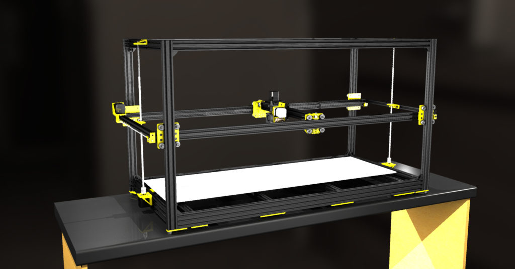
@emily said in Build Log: Fun King 3D FK-1 3D Printer:
Looks like it could be fun. (Pun very much intended). As someone that can't look at any printer without wanting to tinker, I see some things I would want to change.
Honestly, I had to finally just put my foot down and call it good. There are still things I will change, but if I did not just stop this thing would be in the design phase forever! 
Obviously such a large printer is going to have to be built with some compromises without cost getting insane. Otherwise we end up with a $500,000 milling machine.
One of those compromises may be printing primarily with a large diameter nozzle, and tall layer heights. I would rule out printing with a .4mm nozzle. (Might work ok within a smaller portion of the bed), unless it turns out to be rigid enough. Tall layer heights could be more forgiving here.
I have plans to start with a .4 as that is what is already on the hotend and what I run on all of my other printers, but I also have plans to play with other sizes in the future. I want to be able to print larger objects quicker, so the larger diameter is a must. The hotend will be swappable, so I am also planning a 3mm option.
I figure you are already aware of this. Joining the extrusions with blind screw method here would be best. The corner brackets won't do much (Don't ask me how I know this).
All connections with the Openbuilds v-slot will be blind screwed as well as adding the brackets. I built an AM8 from the Anet A8 and it is only bracketed. While it is fairly rigid, I plan to disassemble it and blind screw it as well. (One day. It prints really well and I hate to mess with it. LOL!)
As mentioned earlier. I would go with either 3 or 4 lead screws on the Z axis. 3 is preferable if it works, but I would probably do 4. At this point you probably don't have to worry much about weight with 4 z motors.
I have looked into this and have a couple ideas for options.
Out of curiosity, why would you think it would need more than the 2? (What is the concern?) I won't tell you my thoughts yet, I would like to hear yours to see if we are on the same page.
This design relies a lot on the 20x40 extrusions being perfectly straight with minimal deflection. So maybe this isn't a concern, deflection is acceptable and the extrusions you got are really straight. But this is something I would test.
I would consider going with a 20x60 extrusion on the long axis. More costly option would be to add a linear guides to that. A possible budget oriented solution if the current design is just not working would be to add a second narrower extrusion on the inside of each side with holes drilled regularly along its length for adjustment. This would be kind of tedious to get adjusted but it could work.
The bottom "box" is 2060 which I did to allow the additional fastener to the uprights. (It also allows me 20mm under the cross members that the bed attaches too to allow wires and such to pass.) I did a few (very non scientific) tests and with the length it is running the deflection "shouldn't" be an issue. LOL! 2020 had too much deflection though.
It will be fun to see this progress.
It has been fun to this point for sure and is now getting really exciting.
Thank you for this post. These are all great points.


