Ah I think I may have been a little unclear - I have an E3D Hemera, so my plan was to cause the Hemera stepper to vibrate, which would fulfill a similar function to a phone vibration motor attached to the hotend. That is a good idea though, it'd be easy to connect one to a fan header and I'm sure they are comparable in weight to a bltouch. I'll definitely keep it in mind if I can't figure out a way for the hemera stepper to vibrate.
Posts made by copperbricks
-
RE: Way to purposefully cause stepper to vibrate?posted in General Discussion
-
Way to purposefully cause stepper to vibrate?posted in General Discussion
While searching for alternative Z-Probe ideas (if it ain't broke, fix it some more), I stumbled across this hackaday article: https://hackaday.com/2016/07/18/sonic-3d-printer-auto-bed-leveling-makes-swoosh/ which details using a teensy in conjunction with a piezo sensor to detect a change in vibrations when the nozzle touches the bed (using a the stepper to produce vibrations).
In the article the author uses an extra board in between the control board and stepper driver to cause these vibrations. I was wondering if there's a way to do this in Duet firmware? I was thinking maybe a conditional loop with repeating microsteps in opposite directions, but suspect there may be a more elegant way to do it.
To summarize, my idea is: mount piezo on extruder/x-carriage, cause stepper to vibrate, measure frequency difference when not touching bed and touching bed, then use that data with a teensy to send the Duet 2 a high/low signal to indicate when the nozzle has contacted the bed.
-
RE: Adding status LEDs to microswitch endstop for tool changeposted in Duet Hardware and wiring
@T3P3Tony Got it, thank you! I'll make sure it's a schottky diode.
-
Adding status LEDs to microswitch endstop for tool changeposted in Duet Hardware and wiring
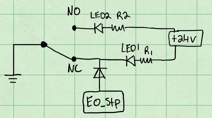
I have a homebuilt Toolchange printer I'm close to finishing and recently added a tool status microswitch to the toolhead to avoid picking up a tool with one already attached and similar errors. I'd also like to add LEDs to indicate the status- LED2 on for tool attached, LED1 for no tool attached. Is the wiring shown below suitable? The only thing I'm not sure on is having the step pin connected to 24v, in my diagram I have a diode but I'm not sure if that would work.

Alternately I can just use two GPIO pins and daemon.g to update the LEDs status but this seems a little simpler.
Thanks
-
RE: Overheating Stepper Motors with Duet Maestroposted in Duet Hardware and wiring
The board is mounted vertically, with venting at the top and whole bottom section of the board. However my issue is the steppers themselves overheating, the mainboard hasn't had any heat issues.
-
Overheating Stepper Motors with Duet Maestroposted in Duet Hardware and wiring
I recently finished building a Prusa MK3-ish printer using a Haribo 3030 frame and some extra parts I had lying around, including a Duet Maestro. It had been working without problems until recently, when I changed some of the stepper motors out (if it works fix it until it doesn't right?). X and Y axis were changed to the Stepperonline 17HM15-0904S, a 0.9 degree 0.9A rated stepper. Z axis motors were changed to integrated leadscrew steppers from a real Prusa, which from my research are rated at 1.0A each.
Since then I've had significant overheating issues on the X and Z axis motors. Originally I had currents set to 600 for the X-Axis and 560 for the Z-axis (stock value from Prusa firmware). However this caused significant overheating, to the point of layer shifts and failed prints. I have checked the motion of both axes by hand and they don't bind or have rough movement.
I have it mostly under control by adding a heatsink to the X motor, reducing motor current and idle current and switching to spreadcycle mode (not sure if it helped but it didn't seem to hurt at least). However this feels wrong to me - I don't think I should need to reduce motor current so significantly to avoid overheating.
Below is my config.g, and I'm running RRF 3.1.1
; Configuration file for Duet Maestro (firmware version 3)
; executed by the firmware on start-up
;
; generated by RepRapFirmware Configuration Tool v2.1.8 on Sun May 10 2020 22:01:12 GMT-0400 (Eastern Daylight Time)

; General preferences
G90                                            ; send absolute coordinates...
M83                                            ; ...but relative extruder moves
M550 P"Ender 3 Pro"                            ; set printer name

M575 P1 S1 B57600		; turn on paneldue

; Network
M552 P192.168.1.14 S1                          ; enable network and set IP address
M553 P255.255.255.0                            ; set netmask
M554 P192.168.1.254                            ; set gateway
M586 P0 S1                                     ; enable HTTP
M586 P1 S0                                     ; disable FTP
M586 P2 S0                                     ; disable Telnet

; Drives
M569 P0 S1   D2                                  ; physical drive 0 goes backwards
M569 P1 S1     D2                                ; physical drive 1 goes backwards
M569 P2 S1       D2                              ; physical drive 2 goes forwards
M569 P3 S0    D2                                 ; physical drive 3 goes backwards and in spreadcycle mode
M569 P4 S1         D2                            ; physical drive 4 goes backwards

M584 X0 Y1 Z2:4 E3                               ; set drive mapping
M350 X16 Y16 Z16 E16 I1                        ; configure microstepping with interpolation
M92 X200.00 Y200.00 Z400.00 E409.00              ; set steps per mm
M566 X480.00 Y480.00 Z20.00 E270.00 P1      ; Set maximum instantaneous speed changes (mm/min)
M203 X12000.00 Y12000.00 Z600.00 E6000.00        ; set maximum speeds (mm/min)
M201 X500.00 Y500.00 Z80.00 E5000.00          ; set accelerations (mm/s^2)
M906 X550 Y600 Z400 E700 I10                  ; set motor currents (mA) and motor idle factor in per cent
M84 S30                                        ; Set idle timeout

; Axis Limits
M208 X-20 Y0 Z0 S1                               ; set axis minima
M208 X220 Y230 Z210 S0                         ; set axis maxima
M671 X-56.5:272.5 Y115:115 S5			; set up dual leadscrews with 5mm allowable compensation

; Endstops
M574 X1 S1 P"xstop"                            ; configure active-high endstop for low end on X via pin xstop
M574 Y1 S1 P"ystop"                            ; configure active-high endstop for high end on Y via pin ystop

; Z-Probe
M558 P9 C"^zprobe.in" H5 F500 T6000 A6 S0.02 B1           ; set Z probe type to bltouch and the dive height + speeds, also set max probes to 6 and tolerance to 0.02mm
G31 P25 X58 Y-10 Z2.215                       ; set Z probe trigger value, offset and trigger height larger offset = closer to bed
M557 X40:220 Y15:220 P6                      ; define mesh grid
M376 H15		;turn off mesh compensation at 15mm
; Heaters

M308 S0 P"bedtemp" Y"thermistor" T100000 B4092 ; configure sensor 0 as thermistor on pin bedtemp
M950 H0 C"bedheat" T0                          ; create bed heater output on bedheat and map it to sensor 0
M143 H0 S125                                   ; set temperature limit for heater 0 to 150C
M307 H0 A164.8 C645.6 D2.6 V24.3 B0            ; disable bang-bang mode for the bed heater and set PWM limit
M140 H0                                        ; map heated bed to heater 0
M308 S1 P"e0temp" Y"thermistor" T100000 B4725 C7.06e-8  ; configure sensor 1 as thermistor on pin e0temp
M950 H1 C"e0heat" T1                           ; create nozzle heater output on e0heat and map it to sensor 1
M143 H1 S300                                   ; set temperature limit for heater 1 to 300C
M307 H1 A727.1 C198.0 D3.3 V24.4 B0

; Fans
M950 F0 C"fan0" Q500                         ; create fan 0 on pin fan0 and set its frequency
M106 P0 S0 H-1                                 ; set fan 0 value. Thermostatic control is turned off
M950 F1 C"!fan1"  Q100                    ; create fan 1 on pin fan1 and set its frequency
M106 P1 S0.7 H1 T45                              ; set fan 1 value. Thermostatic control is turned on


; Tools
M563 P0 D0 H1 F0                               ; define tool 0
G10 P0 X0 Y0 Z0                                ; set tool 0 axis offsets
G10 P0 R0 S0                                   ; set initial tool 0 active and standby temperatures to 0C

; Custom settings are not defined

; Miscellaneous
T0                                             ; select first tool
M950 S0 C"zprobe.mod"

M950 P1 C"TWCK0" ;define GPIO Pin 1
Are there any obvious errors with my config file or any other hardware things I should check?
Thanks
-
AC Heated Bed Wiring Validationposted in Duet Hardware and wiring
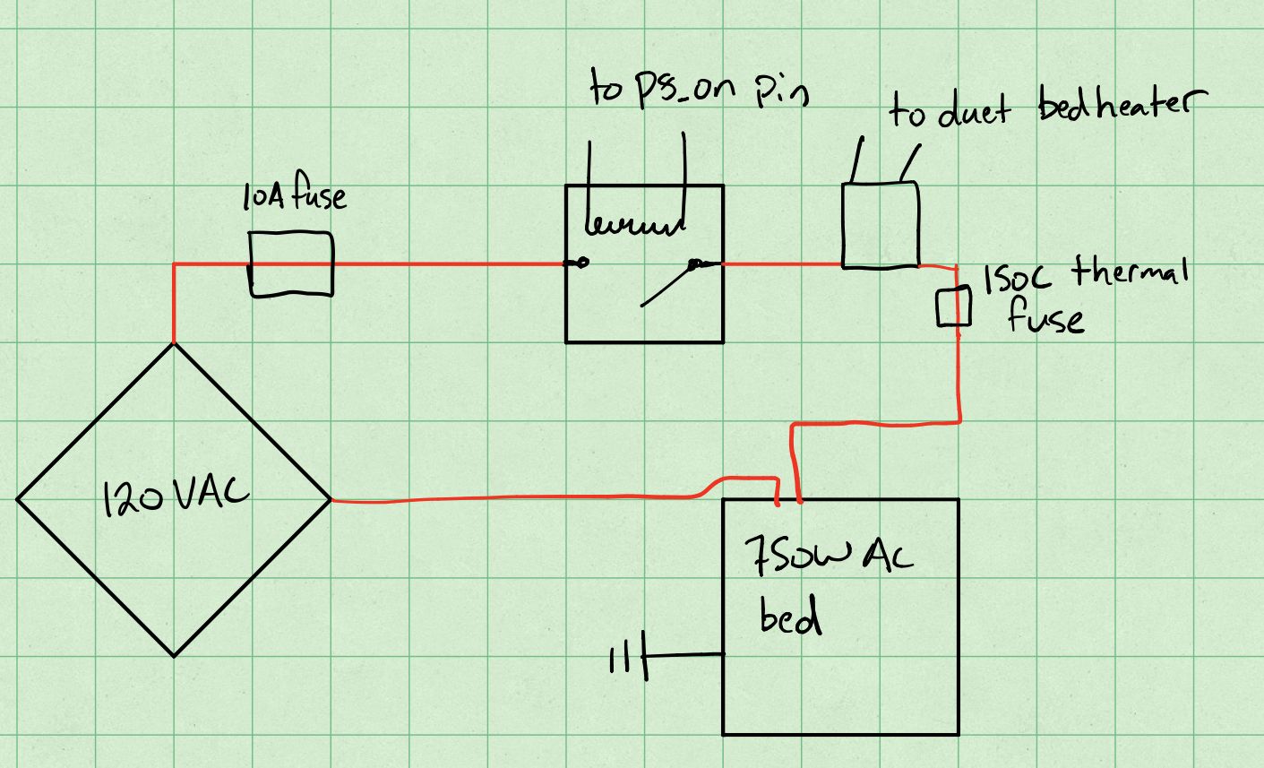
I'm in the process of adding an AC heated bed to my homebuilt printer and wanted to get a check of how I'm planning to wire it before I go ahead.
Components:
- Sensata-Crydom D1225 25A SSR
- Re-settable 10A AC fuse (https://www.amazon.com/RKURCK-Thermal-Breakers-Overload-Protector/dp/B081PFZWFX/ref=sr_1_2?dchild=1&keywords=AC+10A+breaker&qid=1598206431&sr=8-2)
- Cantherm 152C 15A Thermal Cutoff
- Generic Arduino style mechanical relay board
- Generic 750W AC heated bed
- Duet 2 Wifi

Above is the wiring diagram I'm planning on using, grounding the bed and attaching the TCO to the heated bed using high temp RTV silicone. I'm planning on using the mechanical relay in a normally off state as an extra layer of protection.
Does anyone see any issues with my wiring or component choices?
Thanks
-
RE: Fan doesn't run at full speed with PWM controlposted in Duet Hardware and wiring
Hi dc42, thank you for the quick response. Further troubleshooting has shown this to be a pebcak error - I had my fan wires mixed up at the board. I guess I'll have to check other possible causes for heat creep.
-
Fan doesn't run at full speed with PWM controlposted in Duet Hardware and wiring
I've been using this fan on an E3D Hemera and have been running into serious heat creep issues, which didn't make sense as it's a very powerful fan. I have been running it at full speed (tried S1.0 and S255) on a PWM fan header, however I finally tested it on an always on header and it spun a good bit faster. I tested frequencies between 10 and 1kHz with the same result. I think this may be due to some of the anti-stall circuitry etc in the fan not playing nice with PWM.
I'd like to retain temperature control for the fan, so does anyone have any advice for getting its full power out of a PWM header? Or is there a way to set a fan header to simple on/off? I could wire up a discrete relay but I'd like to leave that as a last resort.
Thanks
-
A few conventions questions for a toolchangerposted in General Discussion
I've recently completed a CoreXY Toolchanger of my own design and am currently working on fine tuning the software side. I have two questions with regards to that: Is it better to set the tool offset in config.g, or in tpostX.g? Currently I have it set in config.g but have seen some builds with it in tpostX.g. Along that vein, is it recommended to disable then re-enable mesh bed leveling in tfreeX.g and tpostX.g?
Thanks!
-
RE: Z Height at Start or Tool Changeposted in Tuning and tweaking
@andyvirus I stumbled across this thread with a similar issue to yours. I figured I'd reply in case anyone else finds this thread looking for a solution. I fixed my issue by removing any "T" commands from my Tpost/Tfree/TPre macros. I had a T-1 in the beginning of a few of them and I believe this was causing my G-code for lowering the bed to be run twice.
-
Use a Duet Maestro Expansion board with a Duet 2 Wifi?posted in Duet Hardware and wiring
I'm planning on adding triple motor bed leveling to my printer and need a 6th stepper driver, but unfortunately haven't been able to find the Duex board in stock anywhere. I was however able to find the expansion board for the Maestro. Is there anything stopping me from making a wiring harness to connect it (Maestro board) to the necessary power and GPIO pins of my Duet 2 wifi? I assume I'd have to assign the pins manually in config.g.
Thanks