@Ce72 Hi, thank you for your input and any suggested test are much appreciated. I have tried changing the extruder gears and that unfortunatly had no effect, as for z wobble I would have thought the pattern would be the same on all faces, but what I have noticed is that the pattern changes direction and not on opposite face so it just adds to my confusion

Posts made by Ce72
-
RE: Like Z Banding
-
RE: Like Z Banding
@mikeabuilder Hi, Thank you for your thoughts, but after going down the rabbit hole replacing the SSR and bed heater, I tried running a test print with the bed heater turned off to try and eliminate the bed heater and I still had the same results. but I'm not that clued up on electrics to know if that would negate any effects.
-
RE: Like Z Banding
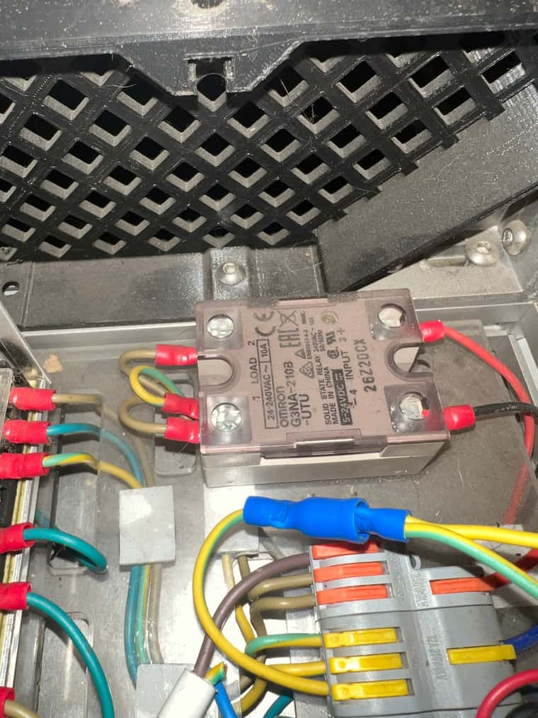
Hi Ian thank you for pointing me in the right direction to set the PID tune.
Then I run some tests to see If the banding had finally gone, unfortunately not so I decided to run some other tests to see if I could isolate the problem or ever just work out what effects the banding pattern.
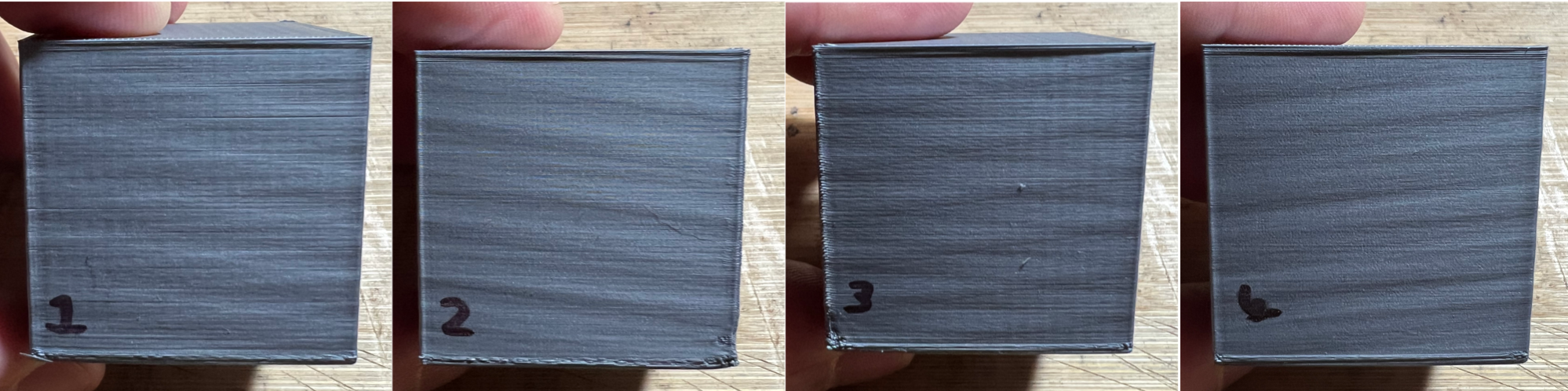
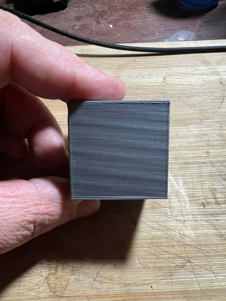
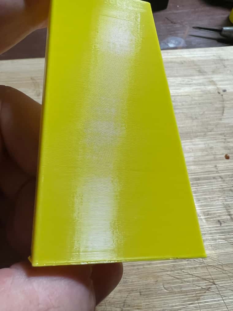
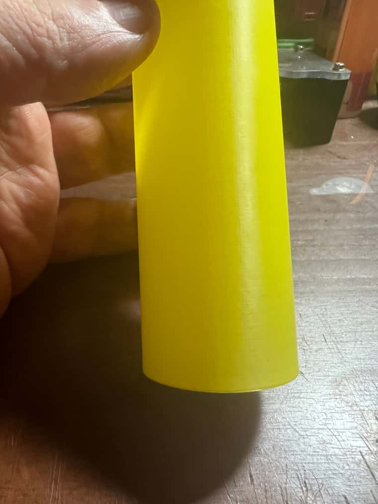
This is the first test print after changing the heater and SSR as well as retuning the extruder PID. banding is the same as before.
The next test I turned off the bed heater after the first couple of layers. To see if the banding was being affected by the bang-bang theory being caused by the bed heater but the banding was still the same. This left me wondering if it was a back to a mechanical issue the good old Z wobble as nothing electrical or extruder seemed to be affecting the outcome.
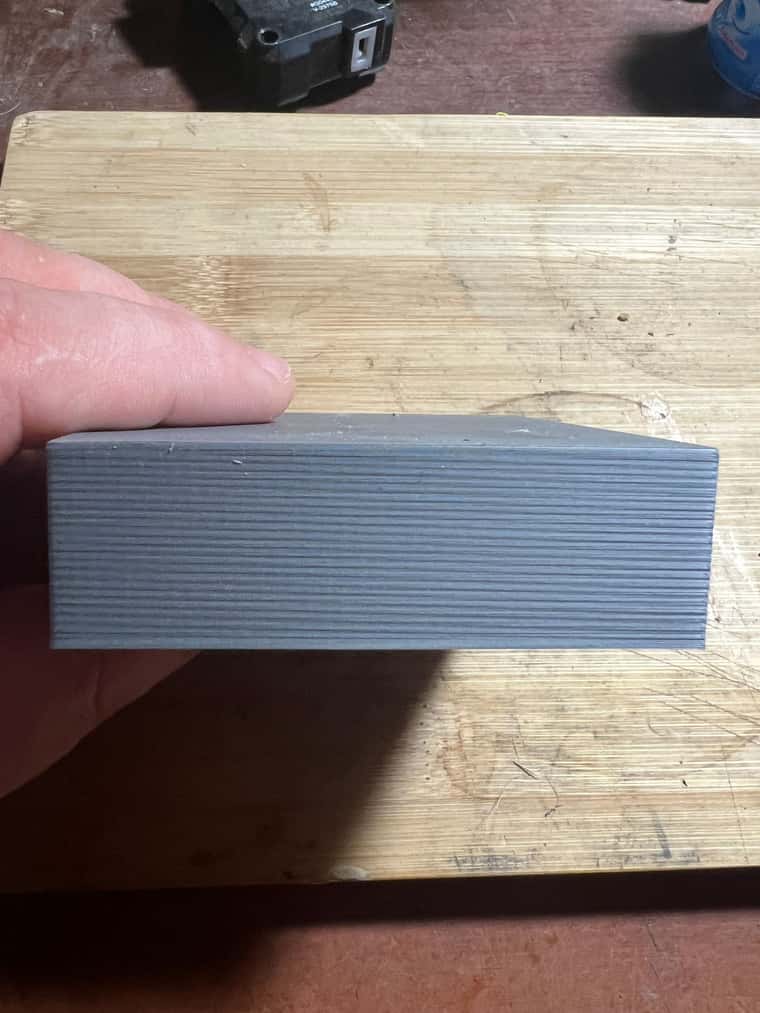
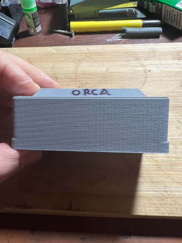
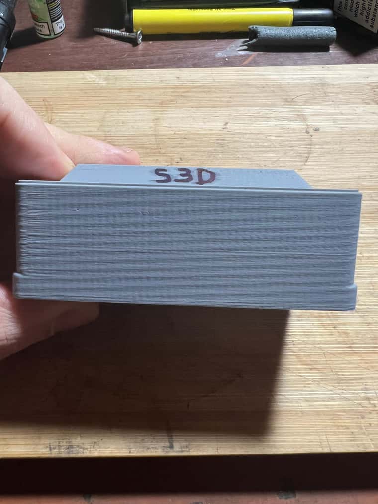
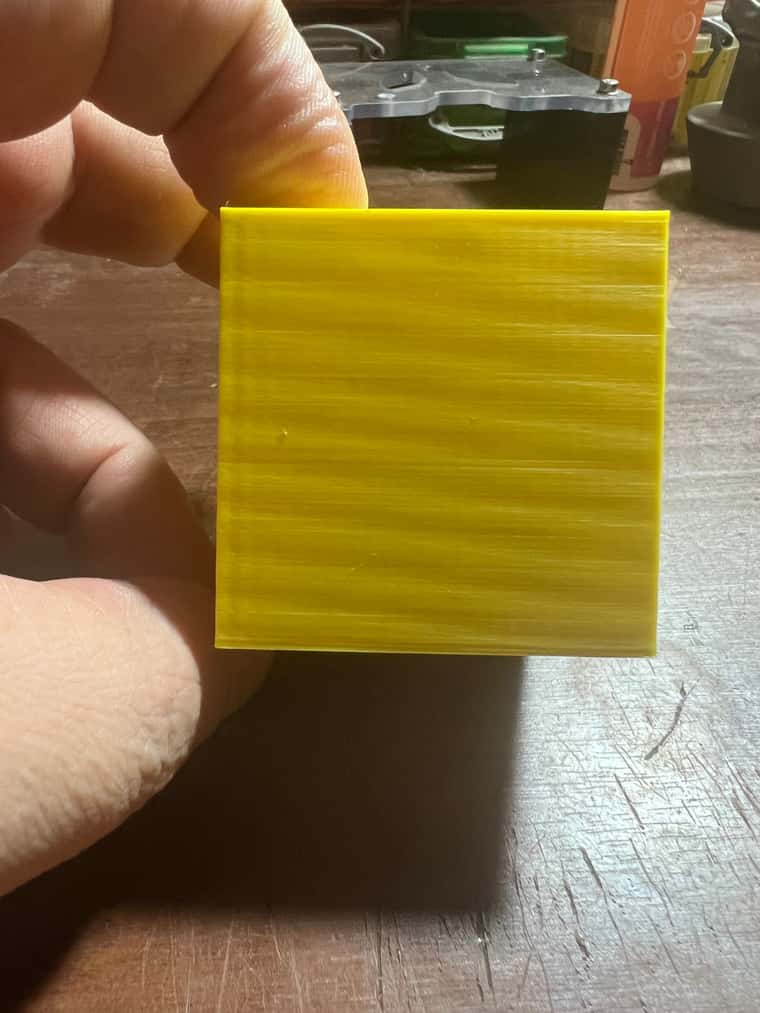
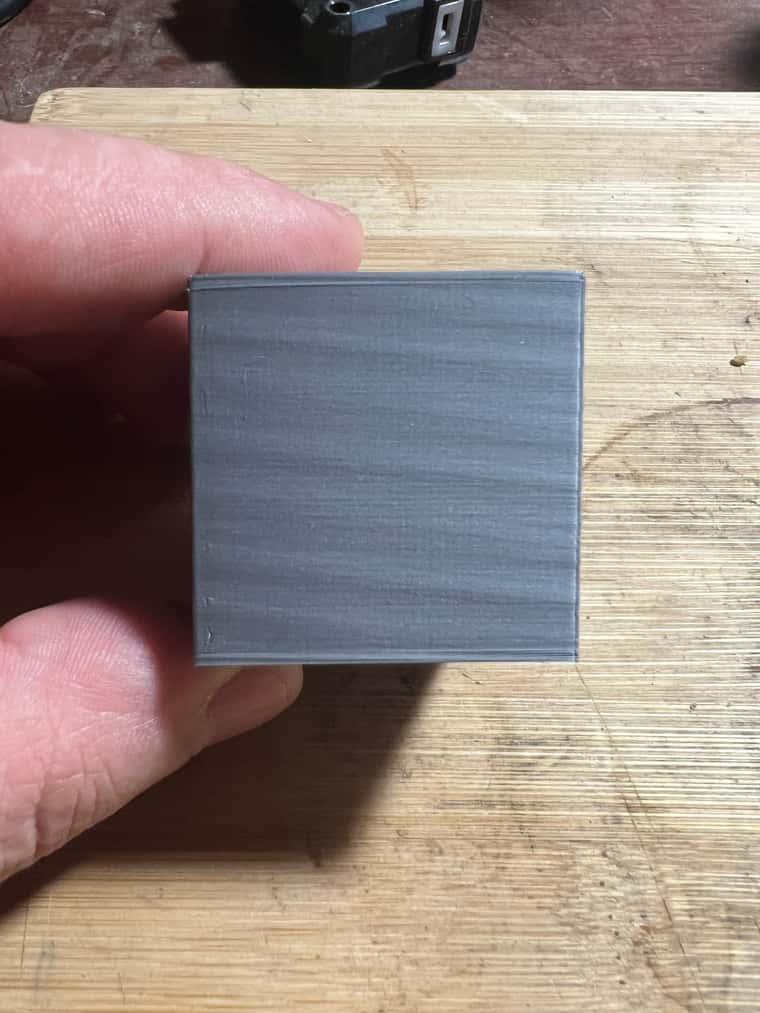
The last test I did after reimaging the pi (hey try anything at this point ) This time I resized the test model from a 40mm cube the a 80mm square by 25mm high same slicing profile as before but this time the banding was a lot closer together than before, To me me this eliminates a mechanical problem as the pattern frequence is so far away from the ball screw pitch.
As mentioned earlier in this thread I have also tried a diffent slicer, so it’s also not that
I’m running out of things to try so any further suggestions from anyonre would be greatly appreciated
And sorry for the long post. -
RE: Like Z Banding
So, this is now confusing, I have replaced the relay and fitted a new Silicon heater back to the original setup, which ran perfectly fine for 2 years. And when I run the PID tuning cycle I now constantly get:
Warning: heater behaviour was not consistent during tuning
M307 H0 R0.779 K0.208:0.000 D5.70 E1.35 S1.00 B0
M307 H0 R0.776 K0.270:0.000 D5.24 E1.35 S1.00 B0
M307 H0 R0.789 K0.265:0.000 D5.85 E1.35 S1.00 B0
M307 H0 R0.779 K0.247:0.000 D5.35 E1.35 S1.00 B0
M307 H0 R0.778 K0.257:0.000 D5.49 E1.35 S1.00 B0Could it be the heater output on the mainboard? Is it possible to use a spare extruder output as I’m running through a relay? To test.
Has anyone got any suggestions?
-
RE: Like Z Banding
@o_lampe Thank you for pointing that out, I have ordered a new heater, and when it's been installed I will post back here the results hopefully it will cure the banding issue.
-
RE: Like Z Banding
@Notepad Well, I have now changed the SSR, but I am still getting some fluctuation, but at least some are fault free. Here are the results:
M307 H0 R0.863 K0.260:0.000 D5.37 E1.35 S1.00 B0 XXXXXX
M307 H0 R0.875 K0.265:0.000 D5.36 E1.35 S1.00 B0 XXXXXX
M307 H0 R0.874 K0.346:0.000 D5.72 E1.35 S1.00 B0
M307 H0 R0.856 K0.307:0.000 D4.85 E1.35 S1.00 B0
M307 H0 R0.852 K0.301:0.000 D5.32 E1.35 S1.00 B0 XXXXXXXXXXXX = Warning: heater behaviour was not consistent during tuning
My next step of thinking down this rabbit hole of fluctuation is, where I have used RTV to refix the silicon heater could the layer be too thick or uneven (It’s not easy stuff to work with) causing a slow transition of heat, resulting in a slow reaction that the PID loop is struggling with?
Does anyone know of anywhere in the UK, where I can get a good 330 x 330mm 240v high temp (I print a lot of ABS and the like) silicon heater. At a good price and quick delivery? As even Keenovo has started using a NTC 100K thermistor on there heaters which from what I understand can be a pain to setup and not that great for the higher temps.
-
RE: Like Z Banding
@droftarts I know theres a better way of doing this but I'm not sure how
; Configuration file for Duet 3 (firmware version 3) ; executed by the firmware on start-up ; ; reconfigured HevORT V1 file for V2.8 on Sat Sep 14 2024 ; ; Port Layout ; Mainboard Ext board ; 0.0 Extruder 1.0 Front Left ; 0.1 Y Back Left 1.1 Rear Middle ; 0.2 Y Front Right 1.2 Front Right ; 0.3 X Back Right ; 0.4 X Front Left ; ; General preferences G4 S2 ; wait for expansion boards to start G90 ; send absolute coordinates... M83 ; ...but relative extruder moves M550 P"HevORT" ; set printer name M669 K1 ; select CoreXY mode ; ; Network ;M552 P0.0.0.0 S1 ; enable network and acquire dynamic address via DHCP ;M586 P0 S1 ; enable HTTP ;M586 P1 S0 ; disable FTP ;M586 P2 S0 ; disable Telnet ; ; Drives M569 P0.0 S1 ; physical drive 0.0 goes forwards Extruder M569 P0.1 S1 ; physical drive 0.1 goes forwards Y1 stepper M569 P0.2 S1 ; physical drive 0.2 goes forwards Y2 stepper M569 P0.3 S1 ; physical drive 0.3 goes forwards X1 stepper M569 P0.4 S1 ; physical drive 0.4 goes forwards X2 stepper M569 P1.0 S1 ; physical drive 1.0 goes forwards Z1 stepper on extension board M569 P1.1 S1 ; physical drive 1.1 goes forwards Z2 stepper on extension board M569 P1.2 S1 ; physical drive 1.2 goes forwards Z3 stepper on extension board M584 E0.0 X0.3:0.4 Y0.1:0.2 Z1.0:1.1:1.2 ; set drive mapping M906 X2096. Y2096. Z1179. E995.6 I30 ; set motor currents (mA) and motor idle factor in percent M917 X70 Y70 Z80 E70 ; Set motor standstill current reduction ;M970 X0 Y0 Z0 E0 ; Enable/disable phase stepping ;M970.1 X1000.0 Y2000.0 Z1000.0 E1000.0 ; Configure phase stepping velocity constant ;M970.2 X50000.0 Y50000.0 Z50000.0 E50000.0 ; Configure phase stepping acceleration constant M84 S30 ; set idle timeout M671 X-28.0:168.35:364.7 Y40.0:348.8:20.0 S10. ; Z leadscrew positions M350 X16 Y16 Z16 E16 I1 ; configure microstepping with interpolation M92 X80.1 Y80.1 Z800.00 E394.00 ; set steps per mm M203 X30000.00 Y30000.00 Z250.00 E1200.00 ; set maximum speeds (mm/min) M201 X20000.0 Y20000.0 Z50.00 E500.00 ; set accelerations (mm/s^2) M204 P10000. T10000. ; Max Acceleration M566 X900. Y900. Z60. E120. ; set maximum instantaneous speed changes (mm/min) M205 X15. Y15. Z1. E2. ; set working instantaneous speed changes (mm/sec) M572 D0 S0.080 ; Preasure advance ; ; Axis Limits M208 X0 Y0 Z0 S1 ; set axis minimium M208 X285.0 Y295.0 Z340 S0 ; set axis maximium ; ; Endstops M574 X1 S1 P"!io0.in" ; configure active-high endstop for low end on X via pin !io0.in M574 Y1 S1 P"io1.in" ; configure active-high endstop for low end on Y via pin !io1.in ; ; Z-Probes ; Probe 1 BL Touch M950 S0 C"io7.out" ; create servo pin 0 for BLTouch M558 K0 P9 C"^io7.in" H10 F300:120 T6000 ; set Z probe type to bltouch and the dive height + speeds ;M558 H30 ;*** Remove this line after delta calibration has been done and new delta parameters have been saved G31 P500 X0. Y-35.09 Z1.65 ; set Z probe trigger value, offset and trigger height ; Probe 2 Scanning Z probe M558 K1 P11 C"120.i2c.ldc1612" F36000 T36000 ; configure SZP as probe 1, type 11, on CAN address 120 G31 K1 Z2.15 Y27. ; define probe 1 offsets and trigger height M558.2 K1 S16 R134773 ; set drive current and reading offset M308 A"SZP coil" S10 Y"thermistor" P"120.temp0" ; thermistor on coil M955 P120.0 I56 ; Add accelerometer on SZP with CAN address 120 and specify orientation M557 X10.0:275.0 Y35.0:285.0 S10 ; define mesh grid ; ; Heaters & Sensors M308 S0 P"temp0" Y"thermistor" T100000 B3950 ; configure sensor 0 as thermistor on pin temp0 BED TEMP M950 H0 C"out0" T0 ; create bed heater output on out0 and map it to sensor 0 M307 H0 R0.859 K0.301:0.000 D4.90 E1.35 S1.00 B0 ; BED HEATER PID SETTINGS M140 H0 ; map heated bed to heater 0 M143 H0 S135 ; set temperature limit for heater 0 to 120C M308 S1 P"temp1" Y"thermistor" T100000 B4725 C7.06e-8 ; configure sensor 1 as Termistor on pin temp1 EXTRUDER TEMP M950 H1 C"out1" T1 ; create nozzle heater output on out1 and map it to sensor 1 M307 H1 R5.007 K0.417:0.603 D2.71 E1.35 S1.00 B0 V23.6 ;M307 H1 R5.395 K0.416:0.839 D2.53 E1.35 S1.00 B0 V23.7 ; PID Tune M143 H1 S300 ; set temperature limit for heater 1 to 300C M308 S2 A"Chamber" P"temp2" Y"thermistor" T100000 B4138 ; configure sensor 0 as thermistor on pin temp2 CHAMBER TEMP SENSOR M308 S3 A"CPAP Pump" P"temp3" Y"pt1000" R2200 ; configure sensor 0 as thermistor on pin temp3 CPAP TEMP SENSOR M308 S11 Y"mcu-temp" A"MCU" ; defines sensor 10 as MCU temperature sensor MCU TEMP SENSOR ;M308 S12 Y"drivers" A"Stepper Drivers" ; defines sensor 11 as stepper driver temperature STEPPER TEMP SENSOR ; ; Fans M950 F0 C"1.out3" ; create fan 0 on pin out3 on Expansion board PART COOLING FAN M106 P0 S0 X180 H-1 ; set fan 0 value. Thermostatic control is turned oFF M950 F1 C"out7" Q250 ; create fan 1 on pin out7 and set its frequency EXTRUDER FAN M106 P1 S1 H1 T45 ; set fan 1 value. Thermostatic control is turned on M950 F2 C"!out5+out5.tach" Q250 ; create fan 2 on pin out5 and set its frequency MCU COOLING FAN M106 P2 H11 T45:60 ; set fan 2 value. Thermostatic control is turned on M950 F3 C"!out6+out6.tach" Q250 ; create fan 3 on pin out6 and set its frequency CHAMBER FAN M106 P3 H2 T30:35 ; set fan 3 value. Thermostatic control is turned on ; ; Tools M563 P0 D0 H1 F0 ; define tool 0 G10 P0 X0 Y0 Z0 ; set tool 0 axis offsets G10 P0 R0 S0 ; set initial tool 0 active and standby temperatures to 0C ; ; Axis Correction M556 S80 X0. Y0. Z0. ; Axis Correction ; ; Input shaping M593 P"mzv" F45.0 S0.1 ; use ZVD input shaping to cancel ringing at 67.0Hz ; Shaping Options "none" "zvd" "zvdd" "zvddd" "mzv" "ei2" "ei3" ;M593 P"none" ; disable input shaping ; ; Custom settings are not defined ; LED Settings ; ;M150 X1 ; Set LED Type ( PRE 3.5.0 FORMAT) M950 E0 C"led" T1 U32 ; create a RGB Neopixel LED strip on the LED port (3.5.0 FORMAT) M150 R255 U255 B255 P200 S10 F1 ; Left side White M150 R31 U81 B255 P220 S11 F1 ; Blue back M150 R255 U255 B255 P200 S10 F0 ; Right side white ; M950 E1 C"io2.out" T1 U10 ; create a RGB Neopixel LED strip in Electric box on the io2 port M150 R255 U255 B255 P200 S10 F0 ; Left side White ; ; Miscellaneous T0 ; Call T0 M501 ; load saved parameters from non-volatile memory
-
RE: Like Z Banding
@Notepad Thank you for posting back to me, I am not fully clued up with electronics, but my understanding is from what your saying is that the heater seems ok, but it could be the relay starting to fail causing the control fluctuation.
I am not sure what you mean by fails deadly, I take it you mean open circuit? I am glad to say when I built the machine, I grounded both the metal bed plate and the relay down to the plug’s earth pin and not just the frame. I know not to take risks with the mains.
The pic shows the relay I am using to clarify, and if that is the case I will replace it before switching the printer on again.
-
RE: Like Z Banding
@o_lampe I have tried a few different PA settings from 0.03 upto 0.08 and it had very little to no effect on the banding unfortunatly.
-
RE: Like Z Banding
@Notepad I might be going a bit off topic for the forum section, but this banding issue has only started since I refixed my beds Keenovo silicon heater with RTV. When I did this there was no signs of damage on the heater but there were areas of the heater not in contact when the bed where the adhesive had let go. I’m no electrician
I have checked the resistance of my heater with a multimetre, and it read 67.2 ohms, working on UK mains being 240v with a 750w heater I worked out it should be around 76.8 ohms. Is this within margin of error?
I carried out a number of M303 PID tunes on the heater letting it return back to room temperature each time. And got these results.
Warning: heater behaviour was not consistent during tuning on all tests
M307 H0 R0.845 K0.256:0.000 D5.16 E1.35 S1.00 B0
M307 H0 R0.854 K0.400:0.000 D5.40 E1.35 S1.00 B0
M307 H0 R0.862 K0.264:0.000 D5.29 E1.35 S1.00 B0
M307 H0 R0.859 K0.301:0.000 D4.90 E1.35 S1.00 B0I’m wondering if these variations are signs of my heater dying? And could this be the route cause of the banding issue only showing up on the longer model prints rather than the short test prints?
Any thoughts??
-
RE: Like Z Banding
@Ce72 Back to confusion 2 prints, 2 slicers, same settings and 2 results
Using Orca slicer 0.2mm layer height
Using S3D slicer 0.2mm layer height
-
RE: Like Z Banding
@droftarts HI Ian, thank you for giving me a nodge to do the woodgrain test properly.
I changed to the 0.4mm nozzle and setup the test for 0.65mm outer wall thickness, 0.3mm layer height at 20mms in vase mode. And this is what happened:
Apart from the slight VFA’s from the slow feed, it is pretty much spot on.
I’m starting to wonder if this is more of a slicer issue as I seem to have the problems when printing models not in vase mode, All along I have been using the same Gcode program for the cube to use as a baseline, which may have been misleading me.
I’ll try using 2 different slicers on the same model to compare the results. I have been using Orca for a while, but I still have a working profile in S3D. I will post up my results
-
RE: Like Z Banding
@droftarts I did print the tower but it was with setting that I have been running 0.25mm nozzle and 0.125 layer height and there was hardly any blemishs, so I didn't mention it
Also since my last post about refitting the heater I have rechecked my wiring connections and run another PID tune.
I will change to a 0.4mm nozzle and rerun the test with the recomended setting of 0.65mm walls and 0.3 layer height in vase mode. then I will post a pic to show my findings.
-
RE: Like Z Banding
I have replaced the drive gears in the extruder and it has made no difference the the pattern, I'm at a bit of a lose. in what to try next if it was down to mechanical Z wobble my thinking is that the pattern would also be on the tube and not just the cube.
Any suggestions or input would be greatly appreciated.
-
RE: Like Z Banding
@Notepad Hi, I built my HevORT 3 years ago this year. Yes, I have been using the WobbleX rings for over a year now. I have even upgraded to the experimental 2.6 (I think) version on the wiki, that I remodelled to suit my setup, I have added the pic so you can see what I mean, But I did this upgrade back in September along with going to AWD and everything has been working fine.
To be honest I have only had this issue start around Christmas when I had to strip the bedplate off to reapply the bed heater as the old adhesive had started to let go. I have done multiple P.I.D tunes to try and see if that eliminates the problem and I have been chasing my tail ever since.
-
RE: Like Z Banding
@droftarts Hi Ian, thank you for your response, and also for the great links. After extensive trawling I also found a helpful video from MirageC pointing me in the same direction.
I'm using the E3D HemeraXS Revo extruder so there's not a lot of wiggle room for modding or testing. I have odered a new set of drive gears to see if that helps, the only other thing I can think of is to try and make an undriven idler for the tension arm. But hopefully it won't come to that.
Once again thank you for the input.
-
Like Z Banding
Hi Everyone
I’m looking for some help and suggestions to try and eliminate a Z banding like artifact on flat surfaces (shown in the pics). I’m running an AWD HevORT core XY with a Hemera XS Roto extruder on a Duet3D 6HC mainboard with a Pi5 SBC, on 3.6.0-beta.3 firmware.To me it’s not mechanical as the 40mm tube pic shows no evidence of the banding.
What I have tried so far:
Bed heater P.I.D tune, Extruder P.I.D tune, Belt tension balanced, Extruder E-steps checked, Various PA values tried, Wall print speeds from 100-200mms And a few acceleration speeds 7000 – 10000 on outerwalls, all with no variation in frequency.Any suggestion to what might be causing this or what else to try would be much appreciated.
-
3.5.0-rc.1 LED Issuse
Hi
I'm using the 6HC mainboard in SBC mode on 3.5.0-rc.1, and I have a Neopixel led strip with 31 LEDs connected to the LED header on the board. When I first power on the machine the LEDs all work fine. However after a short period of time or after running a print, only the first 10 LEDs respond to any commands and the others stay on what they were first set too. so far the only way I have found to clear the issue is to power cycle the whole machine, restarting the mainboard does nothing to help.Is this a software bug or is there somthing I'm missing
-
RE: DWC Temperature dropdowns not working.
@chrishamm Thank you for the suggestion. I used a spare SD card with a fresh full bullseye image, then installed the DSF software as per the link and unfortunately, I ended up back where I started with the dropdowns still not working. I guess it’s the same issues with working with the Bullseye OS. as everything was working perfectly with the Buster install. It’s not a big problem as the machine is still working great. It is only when I want to change materials, I then have to set the temperature remotely (I’m not a great fan of the onscreen keyboard) and ultimately as a work around I can easily create a couple macros to heat up and cooldown until Bullseye is fully compatible.