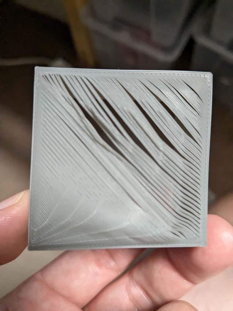
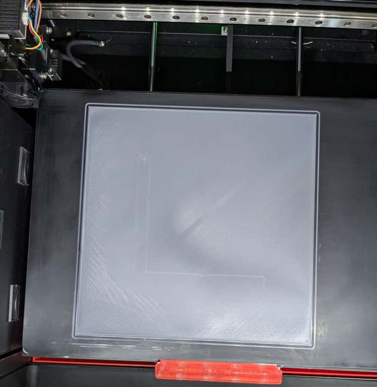
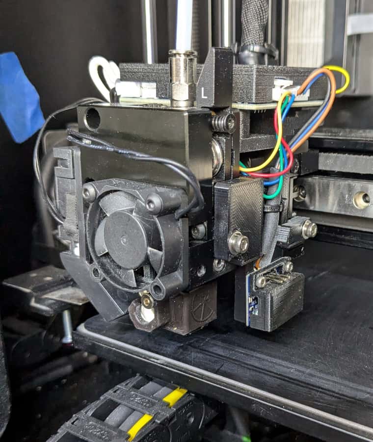
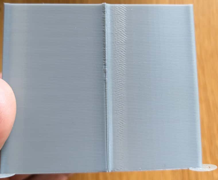
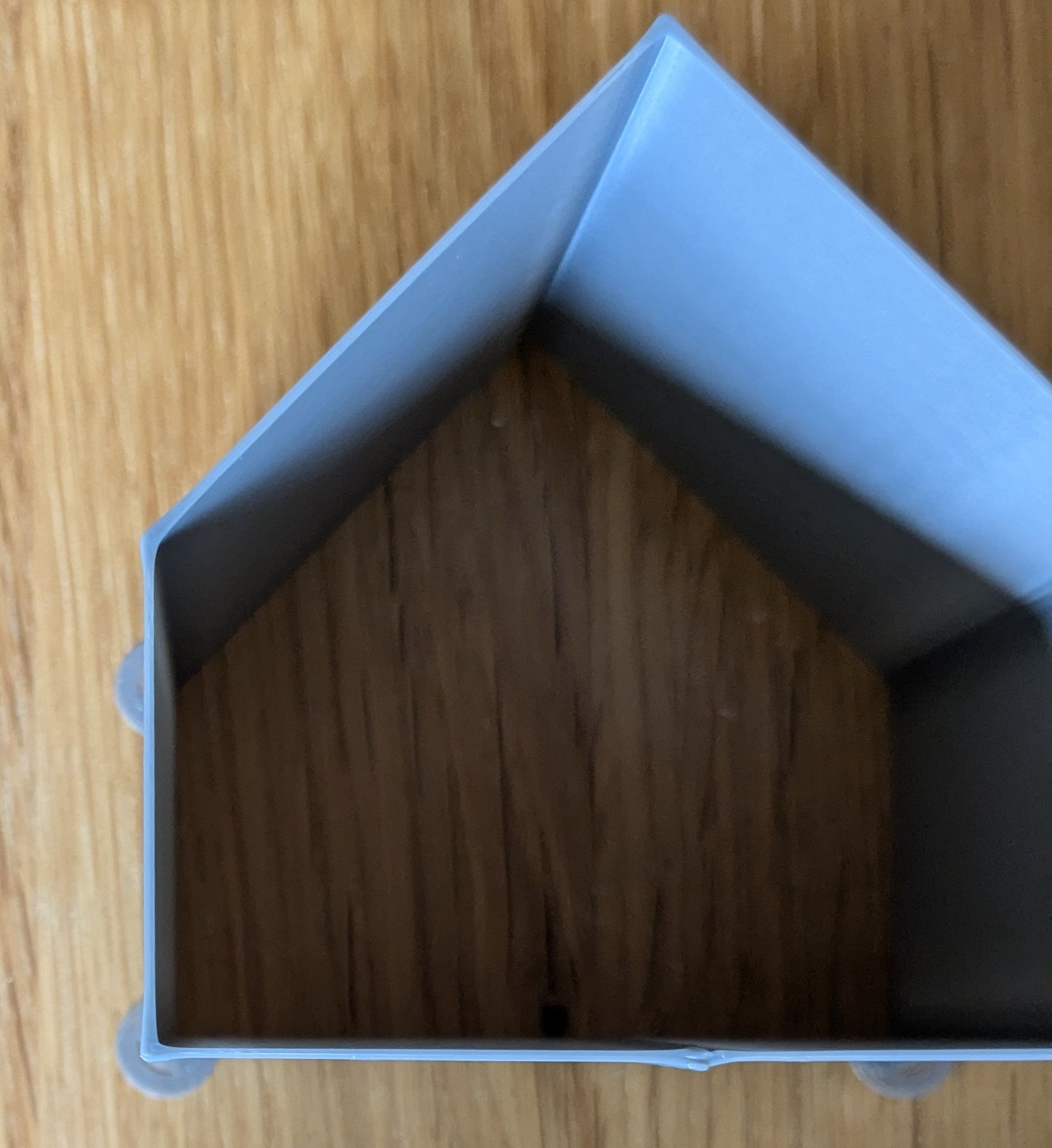
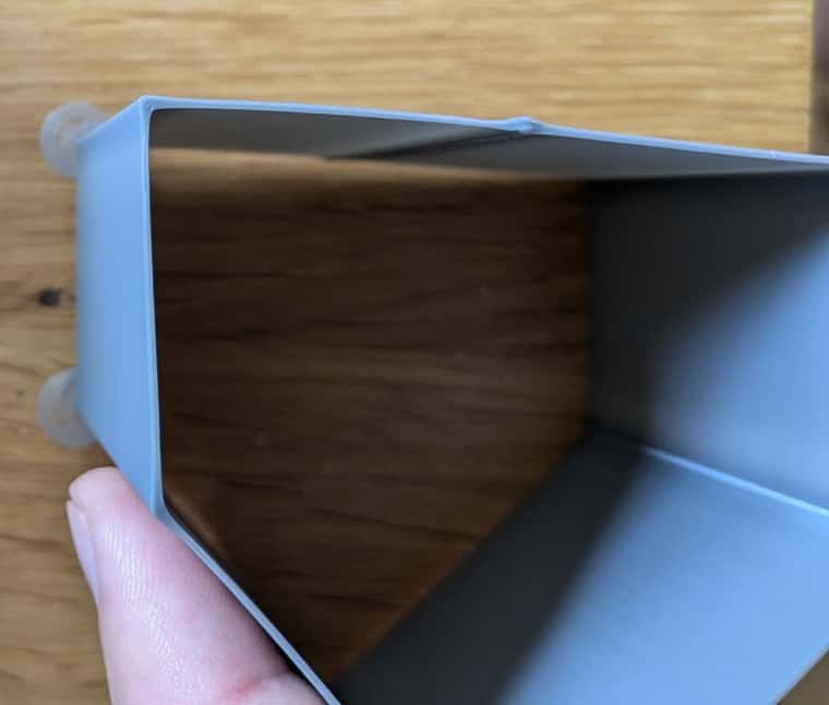
I have now replaced the IR sensor with the BL-Touch and the problem is gone. I think that the different shades on the printing plates caused these errors when using the IR sensors.
Posts made by Anawandur
-
RE: First layer is not evenly closed
-
RE: First layer is not evenly closed
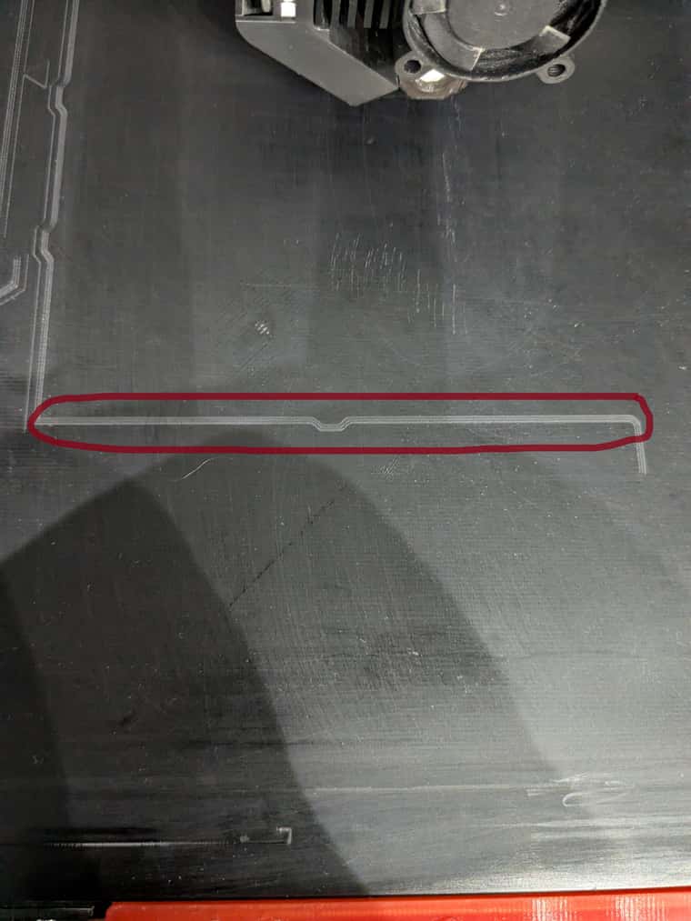
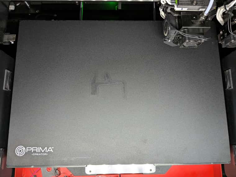
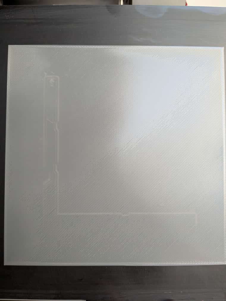
I did a few more tests today. I have different printing plates. On my BlackPrint FR4 (black) I have different mattings due to previous prints or scratched surfaces, which apparently has a big impact on the IR probe.
In the following photo you can see a matting strip, that's exactly where the IR probe measured and found .0.9mm.
.
Then I took a measurement on a BuildTag. There is white writing on the bottom left and in the middle there are marks from an old print. This is also reflected in the heightmap.
.
-
RE: First layer is not evenly closed
@gloomyandy I've already tried it with 15 points. If I use more points, the first layer becomes even more uneven. With 3x3 I get a better result than with 7x7.
I think I have specified the offset correctly, the IR sensor is located at the back right.
Home.z
T-1 P0 G91 ; relative mode G1 H2 Z4 F2000 ; raise head 4mm to ensure it is above the Z probe trigger height G90 ; back to absolute mode G1 H2 X170 Y110 F6000 ; put head over the centre of the bed, or wherever you want to probe M558 F400 G30 ; lower head, stop when probe triggered and set Z to trigger height G1 H0 Z5 F250 M558 F50 A9 S0.003 G30 M558 F200 A1 G1 H1 X-350 U355 Y-2 F3000
-
RE: First layer is not evenly closed
@Phaedrux I created this mesh directly before printing. Since I have big problems with the first layer, the bed is leveled with a macro and the Heightmap.csv is created. Depending on the loaded build plate and filament type, the map is then written to example: Blackprintheightmap60°c, which is then loaded into start.g.
-
RE: First layer is not evenly closed
@dc42 My macro buildplate is loaded in start.g, in which the correct mesh and Z-offset are loaded according to the filament and loaded print plate.
start.g
M291 P"Start.g starting" S0 if !move.axes[0].homed || !move.axes[1].homed || !move.axes[2].homed G28 M98 P"/Macros/SUB/CheckDoor" ;Check whether the door must be opened or closed according to the material M561 ; Disable Mesh Bed Kompensation M106 P3 S25 ; LED 25% M98 P"/Macros/SUB/Preheat" ; Heat Makro G28 Z0 ; Z Home M98 P"/Macros/Buildplate" ;Load buildplate including mesh according to the print plate and take Z-offset into account.
Macros/Buildplate
; check if BuildTak selected is if global.buildplate_type == 1 echo "BuildTak is selected" if (move.extruders[0].filament == "PLA" || move.extruders[1].filament == "PLA") G4 S1 M291 P"BuildTak PLA 60°C" R"Heightmap loaded" S0 T4 M290 R0 S0 ; Reset baby steps M300 S800 P1000 G29 S1 P"BuildTakheightmap60c.csv" ;G4 S2 ;M290 S-0.20 ; Baby Stepp is setting ;echo "Babystep for Buildtak is 0.04mm" if (move.extruders[0].filament == "PETG" || move.extruders[1].filament == "PETG") G4 S1 M291 P"BuildTak PETG 70°C" R"Heightmap loaded" S0 T4 M290 R0 S0 ; Reset baby steps M300 S800 P1000 G29 S1 P"BuildTakheightmap70c.csv" ;G4 S2 ;M290 S0.04 ; Baby Stepp is setting ;echo "Babystep for Buildtak is 0.04mm" if (move.extruders[0].filament == "ASA" || move.extruders[1].filament == "ASA") G4 S1 M291 P"BuildTak ASA 100°C" R"Heightmap loaded" S0 T4 M290 R0 S0 ; Reset baby steps M300 S800 P1000 G29 S1 P"BuildTakheightmap100c.csv" ;G4 S2 ;M290 S0.04 ; Baby Stepp is setting ;echo "Babystep for Buildtak is 0.04mm" if (move.extruders[0].filament == "PA12CF" || move.extruders[1].filament == "PA12CF") G4 S1 M291 P"BuildTak PA12CF 90°C" R"Heightmap loaded" S0 T4 M290 R0 S0 ; Reset baby steps M300 S800 P1000 G29 S1 P"BuildTakheightmap90c.csv" ;G4 S2 ;M290 S0.04 ; Baby Stepp is setting ;echo "Babystep for Buildtak is 0.04mm" ;--------------------------------------------------------------------------------------------------------------------------------------- ;check if PEIglatt selected is if global.buildplate_type == 2 echo "PEIglatt is selected" if (move.extruders[0].filament == "PLA" || move.extruders[1].filament == "PLA") G4 S1 M291 P"PEIglatt PLA 60°C" R"Heightmap loaded" S0 T4 M290 R0 S0 ; Reset baby steps M300 S800 P1000 G29 S1 P"PEIglattheightmap60c.csv" ;G4 S2 ;M290 S0.04 ; Baby Stepp is setting ;echo "Babystep for PEIglatt is 0.04mm" if (move.extruders[0].filament == "PETG" || move.extruders[1].filament == "PETG") G4 S1 M291 P"PEIglatt PETG 70°C" R"Heightmap loaded" S0 T4 M290 R0 S0 ; Reset baby steps M300 S800 P1000 G29 S1 P"PEIglattheightmap70c.csv" ;G4 S2 ;M290 S-0.20 ; Baby Stepp is setting ;echo "Babystep for PEIglatt is -0.20mm" if (move.extruders[0].filament == "ASA" || move.extruders[1].filament == "ASA") G4 S1 M291 P"PEIglatt ASA 100°C" R"Heightmap loaded" S0 T4 M290 R0 S0 ; Reset baby steps M300 S800 P1000 G29 S1 P"PEIglattheightmap100c.csv" ;G4 S2 ;M290 S0.04 ; Baby Stepp is setting ;echo "Babystep for PEIglatt is 0.04mm" if (move.extruders[0].filament == "PA12CF" || move.extruders[1].filament == "PA12CF") G4 S1 M291 P"Peiglatt PA12CF 90°C" R"Heightmap loaded" S0 T4 M290 R0 S0 ; Reset baby steps M300 S800 P1000 G29 S1 P"PEIglatthighmap90c.csv" ;G4 S2 ;M290 S0.04 ; Baby Stepp is setting ;echo "Babystep for Buildtak is 0.04mm" ;--------------------------------------------------------------------------------------------------------------------------------------- ; check if FR4dünn selected is if global.buildplate_type == 3 echo "FR4dünn is selected" if (move.extruders[0].filament == "PLA" || move.extruders[1].filament == "PLA") G4 S1 M291 P"FR4dünn PLA 60°C" R"Heightmap loaded" S0 T4 M290 R0 S0 ; Reset baby steps M300 S800 P1000 G29 S1 P"FR4dünnheightmap60c.csv" G4 S2 M290 S0.20 ; Baby Stepp is setting echo "Babystep for FR4dünn PLA is +0.20 mm" if (move.extruders[0].filament == "PETG" || move.extruders[1].filament == "PETG") G4 S1 M290 R0 S0 ; Reset baby steps M291 P"FR4dünn PETG 85°C" R"Heightmap loaded" S0 T4 M300 S800 P1000 G29 S1 P"FR4dünnheightmap85c.csv" G4 S2 M290 S0.20 ; Baby Stepp is setting ;M300 S2000 P1000 echo "Babystep for FR4dünn PETG is +0.20 mm" if (move.extruders[0].filament == "ASA" || move.extruders[1].filament == "ASA") G4 S1 M291 P"FR4dünn ASA 85°C" R"Heightmap loaded" S0 T4 M290 R0 S0 ; Reset baby steps M300 S800 P1000 G29 S1 P"FR4dünnheightmap100c.csv" G4 S2 M290 S0.20 ; Baby Stepp is setting echo "Babystepp für FR4dünn ASA is +0.20 mm" if (move.extruders[0].filament == "PA12CF" || move.extruders[1].filament == "PA12CF") G4 S1 M291 P"FR4dünn PA12CF 90°C" R"Heightmap loaded" S0 T4 M290 R0 S0 ; Reset baby steps M300 S800 P1000 G29 S1 P"FR4dünnheightmap90c.csv" G4 S2 M290 S0.20 ; Baby Stepp is setting echo "Babystep for FR4dünn PA12CF is +0,12 mm" ;--------------------------------------------------------------------------------------------------------------------------------------- ; check if BlackPrint selected is if global.buildplate_type == 4 echo "BlackPrint is selected" if (move.extruders[0].filament == "PLA" || move.extruders[1].filament == "PLA") G4 S1 M291 P"BlackPrint PLA 60°C" R"Heightmap loaded" S0 T4 M290 R0 S0 ; Reset baby steps M300 S800 P1000 G29 S1 P"BlackPrintheightmap60c.csv" ;G4 S2 ;M290 S-0.12 ; Baby Stepp is setting ;echo "Babystepp für BlackPrint is -0.12mm" if (move.extruders[0].filament == "PETG" || move.extruders[1].filament == "PETG") G4 S1 M290 R0 S0 ; Reset baby steps M291 P"BlackPrint PETG 85°C" R"Heightmap loaded" S0 T4 M300 S800 P1000 G29 S1 P"BlackPrintheightmap85c.csv" ;G4 S2 ;M290 S-0.12 ; Baby Stepp is setting ;M300 S2000 P1000 ;echo "Babystepp für BlackPrint is -0.12mm" if (move.extruders[0].filament == "ASA" || move.extruders[1].filament == "ASA") G4 S1 M291 P"BlackPrint ASA 85°C" R"Heightmap loaded" S0 T4 M290 R0 S0 ; Reset baby steps M300 S800 P1000 G29 S1 P"BlackPrintheightmap100c.csv" ;G4 S2 ;M290 S-0.12 ; Baby Stepp is setting ;echo "Babystepp für BlackPrint is -0.12mm" if (move.extruders[0].filament == "PA12CF" || move.extruders[1].filament == "PA12CF") G4 S1 M291 P"BlackPrint PA12CF 90°C" R"Heightmap loaded" S0 T4 M290 R0 S0 ; Reset baby steps M300 S800 P1000 G29 S1 P"BlackPrintheightmap90c.csv" ;G4 S2 ;M290 S0.04 ; Baby Stepp is setting ;echo "Babystep for Buildtak is 0.04mm"
-
RE: Bed Leveling only on Print Aerea
@jay_s_uk Thank you very much, this works very well.
-
No sharp corners
Hello everyone,
I have converted my Raise3d E2 to a Duet mini5 and 2 LC1 Toolboards and IR Z-Probe and have 2 problems that I cannot solve.
RepRapFirmware 3.6.0-alpha.4+3
I would like to describe problem 2 here and I have opened a new entry for the first one.
Link to Problem 1I have configured my input shaper and came up with a value of M593 F51 S0.2 P"zvddd". I determined my pressure advance to be M572 D0 S0.065.
I always have dirty corners when printing square components. It doesn't matter whether I turn pressure advance on or off. Even a test from 0 to 0.2 didn't bring any improvement to the corners.
I have already found older entries in the forum but still no solution.
Can anyone help?
config.g
; Configuration file for Duet 3 Mini 5+ (firmware version 3.3) ; executed by the firmware on start-up ; ; generated by RepRapFirmware Configuration Tool v3.3.15 on Sat Nov 26 2022 13:27:47 GMT+0100 (Mitteleuropäische Normalzeit) ;########################################################################################################################### ; General preferences ;########################################################################################################################### M575 P1 S1 B57600 ; enable support for PanelDue G90 ; send absolute coordinates... M83 ; ...but relative extruder moves M550 P"Raise 3D E2" ; set printer name ;########################################################################################################################## ; Network ;########################################################################################################################## M552 S1 ; enable network M586 P0 S1 ; enable HTTP M586 P1 S1 ; disable FTP M586 P2 S0 ; disable Telnet ;########################################################################################################################## ; Drives ;########################################################################################################################## M569 P0.0 S0 D3 H50 V30 ; physical drive 0.0 goes forwards M915 P0.0 T50 M569 P0.1 S0 D3 H50 V30 ; physical drive 0.1 goes forwards M915 P0.1 T30 M569 P0.2 S0 D3 H50 V30 ; physical drive 0.2 goes forwards M915 P0.2 T50 M569 P20.0 S0 ; physical drive 0.3 goes forwards Extruder links M569 P0.4 S0 D3 H50 V30 ; physical drive 0.4 goes forwards M915 P0.4 T50 M569 P21.0 S1 ; physical drive 0.5 goes forwards M584 X0.0 Y0.1 Z0.2 E20.0:21.0 U4 ; set drive mapping M350 X16 Y16 U16 Z16 E16:16 I1 ; configure microstepping without interpolation M92 X80 Y80 U80 Z800 E286.216 :286.216 ; set steps per mm linker Extruder : rechter Extroder M566 X600 Y600 U600 Z30 E300:300 ; set maximum instantaneous speed changes (mm/min) M203 X10000 U10000 Y9000 Z600 E3000:3000 ; set maximum speeds (mm/min) M201 X1500 U1500 Y1500 Z120 E3000:3000 ; set accelerations (mm/s^2) ;M906 X850 U850 Y850 Z800 E800:800 I30 ; set motor currents (mA) and motor idle factor in per cent M906 X1200 U1200 Y1200 Z900 E800:800 I30 ; set motor currents (mA) and motor idle factor in per cent M84 S30 ; Set idle timeout ;########################################################################################################################## ; Axis Limits ;########################################################################################################################## M208 X10 Y-3 Z0 U35 S1 ; set axis minima M208 X335 Y255 Z240 U355 S0 ; set axis maxima ;########################################################################################################################## ; Endstops ; configure switch-type (e.g. microswitch) endstop for high end on Z via pin null ;########################################################################################################################## M574 Y1 S1 P"io1.in" M574 X1 S1 P"io2.in" M574 U2 S1 P"Io4.in" ;M915 X S-63 H10 R1 ; Set very sensitive stall detect ;M574 X1 S3 ; configure endstop for stall detection ;M915 X S20 H140 R0 ; Set very sensitive stall detect ;M915 X S-63 H10 R1 ; Set very sensitive stall detect ;########################################################################################################################## ; Switch ;########################################################################################################################## M950 J1 C"SPI.CS2" ;M581 P1 S0 T5 R0 ;Alarm wenn tür beim drucken geöffnet wird ;M581 P1 S1 T6 R0 ;TEST war vorher nicht drin ;########################################################################################################################## ; Filament Sensoren ;########################################################################################################################## M591 D1 P1 C"io6.in" S1 M591 D0 P1 C"io5.in" S1 ;########################################################################################################################## ; Z-Probe ;########################################################################################################################## M558 P8 C"20.io0.in" H5 A7 S0.008 F200 T10000 ; P=Sondentyp C=Eingangspin H=Anfahrhöhe A=Anzahl Tastvorgänge S=Tolleranz (Standard 0,03) F=Abtastgeschwindigkeit T=Verfahrgeschwindigkeit G31 P500 X17 Y21 Z1.30 ; set Z probe trigger value, offset and trigger height + Tiefer - höher M557 X31:335 Y20:225 P7 ; define mesh grid ;########################################################################################################################## ;Acclerometer ;########################################################################################################################## M955 P20.0 I24 ; configure accelerometer on toolboard with CAN address 121 and specify orientation M593 F51 S0.2 P"zvddd" M955 P21.0 I24 ; configure accelerometer on toolboard with CAN address 121 and specify orientation ;########################################################################################################################## ; Heaters ;########################################################################################################################## M308 S0 P"Temp0" Y"thermistor" T100000 B4138 ; configure sensor 0 as thermistor on pin temp0 M950 H0 C"out0" T0 ; create bed heater output on out0 and map it to sensor 0 M307 H0 B1 S1.00 ; enable bang-bang mode for the bed heater and set PWM limit M140 H0 ; map heated bed to heater 0 M143 H0 S120 ; set temperature limit for heater 0 to 120C M308 S2 P"21.Temp0" Y"thermistor" T100000 B4725 C7.06e-8 ; configure sensor 2 as thermistor on pin temp2 M950 H2 C"21.out0" T2 ; create nozzle heater output on out2 and map it to sensor 2 M307 H2 B0 S1.00 ; disable bang-bang mode for heater and set PWM limit M143 H2 S340 ; set temperature limit for heater 2 to 340C M308 S1 P"20.Temp0" Y"thermistor" T100000 B4725 C7.06e-8 ; configure sensor 2 as thermistor on pin temp2 M950 H1 C"20.out0" T1 ; create nozzle heater output on out2 and map it to sensor 2 M307 H1 B0 S1.00 ; disable bang-bang mode for heater and set PWM limit M143 H1 S340 ; set temperature limit for heater 2 to 340C ;########################################################################################################################## ; Temp Sensoren ;########################################################################################################################## M308 S10 Y"mcu-temp" A"MCU" ; defines sensor 10 as MCU temperature sensor M308 S11 Y"drivers" A"Duet stepper drivers" ; defines sensor 11 as stepper driver temperature sensor ;M950 F5 C"out6" Q500 ; create fan 2 on pin fan2 and set its frequency ;M106 P5 H3 T40:70 ; set fan 2 value ;########################################################################################################################## ; Fans ;########################################################################################################################## ;M950 F0 C"vfd" Q500 ; create fan 0 on pin out4 and set its frequency ;M106 P0 C"Bauteil-Lüfter L" S0 H-1 M950 F0 C"20.out1" Q500 M106 P0 C"Bauteil-Lüfter L" S0 H-1 M950 F1 C"21.out1" Q500 M106 P1 C"Bauteil-Lüfter R" S0 H-1 M950 F3 C"out5" Q500 ; create fan 2 on pin vfd and set its frequency M106 P3 C"LED" S150 H-1 ; set fan 2 value. Thermostatic control is turned off M950 F4 C"out4+out4.tach" Q25000 M106 P4 C"Filter-Lüfter" S0 H-1 M950 F5 C"21.out2" Q500 ; create fan 0 on pin out3 and set its frequency M106 P5 C"Hotend Fan rechts" S1 H2 T45 ; set fan 0 name and value. Thermostatic control turned on for Hotend M950 F6 C"20.out2" Q500 ; create fan 0 on pin out3 and set its frequency M106 P6 C"Hotend Fan links" S1 H1 T45 ;########################################################################################################################## ; Create a tool that uses the low end (X) carriage ;########################################################################################################################## M563 P0 D0 H1 F0 S"linker Extruder" ; tool 0 uses extruder 0, heater 1 and fan 0 (P=Werkzeug Nr., S=Name, D=Extruder Motor, H=Heizung, F=Bautellüfter) G10 P0 X0 Y0 Z0 S0 R0 ; set tool 0 offsets and temperatures ;########################################################################################################################## ; Create a tool that uses the high end (U) carriage ;########################################################################################################################## M563 P1 D1 H2 X3 F1 S"rechter Extruder" ; tool 1 uses extruder 1, heater 2, fan 2, and maps X to U G10 P1 Y0.1 U26.6 Z0.02 R0 ; set tool 1 offsets and temperatures für Z: + Tiefer - höher U: - weiter nach rechts + weiter nach links (G10 P1 Y0 U27.0 Z0.02 R0) ;########################################################################################################################## ; Create a tool that prints 2 copies of the object using both carriages ;########################################################################################################################## M563 P2 D0:1 H1:2 X0:3 F0:0 S"Duplikation" ; tool 2 uses both extruders, hot end heaters and fans, and maps X to both X and U G10 P2 X-25 Y0 U-176.3 Z0 S0 R0 ; set tool offsets and temperatures ;G10 P2 X10 Y0 U-176.3 Z0 S0 R0 ; set tool offsets and temperatures ;G10 P2 X0 Y0 U-40 Z0 S0 R0 ; set tool offsets and temperatures G10 P2 R0 S0 M567 P2 E1:1 ; set mix ratio 100% on both extruders ;########################################################################################################################## ;Create a tool that Prints in Mirrior Mode ;########################################################################################################################## ;M563 P3 H1:2 D0:1 X0:3 F0:0 S"Spiegeln" ;G10 P3 X-25 Y0 U-176.3 Z0 S0 R0 ;G10 P3 R0 S-2 ;########################################################################################################################## ; Custom settings are not defined ;########################################################################################################################## ;########################################################################################################################## ;Temperatur anpassung MCU ;########################################################################################################################## M912 P0 S2 ;########################################################################################################################## ; Miscellaneous ;########################################################################################################################## M501 ; load saved parameters from config-override.g M911 S10 R11 P"M913 X0 Y0 G91 M83 G1 Z3 E-5 F1000" ; set voltage thresholds and actions to run on power loss M98 P"GlobaleBuildplate.g" G4 S2 ; wait for expansion boards to start
PA TEST 0 to 0.2
-
First layer is not evenly closed
Hello everyone,
I have converted my Raise3d E2 to a Duet mini5 and 2 LC1 Toolboards and IR Z-Probe and have 2 problems that I cannot solve.
I would like to describe problem 1 here and I will open a new entry for the second. Link to problem 2
The first problem is that my first layer is not evenly closed. When I print one layer (180x180 mm) the first layer has a thickness of between 0.18mm and 0.26mm. The hardware on the printer is very solid and has no problems. I did not have these problems before the conversion either. Perhaps someone can give me tips on where I could look for the error.
My bed leveling is controlled by a macro that creates a Heightmap.csv depending on the print plate and filament used and then saves this in a BlackPrint 60°C file, which is called up in Start.g when printing.
RepRapFirmware 3.6.0-alpha.4+3
config.g:
; Configuration file for Duet 3 Mini 5+ (firmware version 3.3) ; executed by the firmware on start-up ; ; generated by RepRapFirmware Configuration Tool v3.3.15 on Sat Nov 26 2022 13:27:47 GMT+0100 (Mitteleuropäische Normalzeit) ;########################################################################################################################### ; General preferences ;########################################################################################################################### M575 P1 S1 B57600 ; enable support for PanelDue G90 ; send absolute coordinates... M83 ; ...but relative extruder moves M550 P"Raise 3D E2" ; set printer name ;########################################################################################################################## ; Network ;########################################################################################################################## M552 S1 ; enable network M586 P0 S1 ; enable HTTP M586 P1 S1 ; disable FTP M586 P2 S0 ; disable Telnet ;########################################################################################################################## ; Drives ;########################################################################################################################## M569 P0.0 S0 D3 H50 V30 ; physical drive 0.0 goes forwards M915 P0.0 T50 M569 P0.1 S0 D3 H50 V30 ; physical drive 0.1 goes forwards M915 P0.1 T30 M569 P0.2 S0 D3 H50 V30 ; physical drive 0.2 goes forwards M915 P0.2 T50 M569 P20.0 S0 ; physical drive 0.3 goes forwards Extruder links M569 P0.4 S0 D3 H50 V30 ; physical drive 0.4 goes forwards M915 P0.4 T50 M569 P21.0 S1 ; physical drive 0.5 goes forwards M584 X0.0 Y0.1 Z0.2 E20.0:21.0 U4 ; set drive mapping M350 X16 Y16 U16 Z16 E16:16 I1 ; configure microstepping without interpolation M92 X80 Y80 U80 Z800 E286.216 :286.216 ; set steps per mm linker Extruder : rechter Extroder M566 X600 Y600 U600 Z30 E300:300 ; set maximum instantaneous speed changes (mm/min) M203 X10000 U10000 Y9000 Z600 E3000:3000 ; set maximum speeds (mm/min) M201 X1500 U1500 Y1500 Z120 E3000:3000 ; set accelerations (mm/s^2) ;M906 X850 U850 Y850 Z800 E800:800 I30 ; set motor currents (mA) and motor idle factor in per cent M906 X1200 U1200 Y1200 Z900 E800:800 I30 ; set motor currents (mA) and motor idle factor in per cent M84 S30 ; Set idle timeout ;########################################################################################################################## ; Axis Limits ;########################################################################################################################## M208 X10 Y-3 Z0 U35 S1 ; set axis minima M208 X335 Y255 Z240 U355 S0 ; set axis maxima ;########################################################################################################################## ; Endstops ; configure switch-type (e.g. microswitch) endstop for high end on Z via pin null ;########################################################################################################################## M574 Y1 S1 P"io1.in" M574 X1 S1 P"io2.in" M574 U2 S1 P"Io4.in" ;M915 X S-63 H10 R1 ; Set very sensitive stall detect ;M574 X1 S3 ; configure endstop for stall detection ;M915 X S20 H140 R0 ; Set very sensitive stall detect ;M915 X S-63 H10 R1 ; Set very sensitive stall detect ;########################################################################################################################## ; Switch ;########################################################################################################################## M950 J1 C"SPI.CS2" ;M581 P1 S0 T5 R0 ;Alarm wenn tür beim drucken geöffnet wird ;M581 P1 S1 T6 R0 ;TEST war vorher nicht drin ;########################################################################################################################## ; Filament Sensoren ;########################################################################################################################## M591 D1 P1 C"io6.in" S1 M591 D0 P1 C"io5.in" S1 ;########################################################################################################################## ; Z-Probe ;########################################################################################################################## M558 P8 C"20.io0.in" H5 A7 S0.008 F200 T10000 ; P=Sondentyp C=Eingangspin H=Anfahrhöhe A=Anzahl Tastvorgänge S=Tolleranz (Standard 0,03) F=Abtastgeschwindigkeit T=Verfahrgeschwindigkeit G31 P500 X17 Y21 Z1.30 ; set Z probe trigger value, offset and trigger height + Tiefer - höher M557 X31:335 Y20:225 P7 ; define mesh grid ;########################################################################################################################## ;Acclerometer ;########################################################################################################################## M955 P20.0 I24 ; configure accelerometer on toolboard with CAN address 121 and specify orientation M593 F51 S0.2 P"zvddd" M955 P21.0 I24 ; configure accelerometer on toolboard with CAN address 121 and specify orientation ;########################################################################################################################## ; Heaters ;########################################################################################################################## M308 S0 P"Temp0" Y"thermistor" T100000 B4138 ; configure sensor 0 as thermistor on pin temp0 M950 H0 C"out0" T0 ; create bed heater output on out0 and map it to sensor 0 M307 H0 B1 S1.00 ; enable bang-bang mode for the bed heater and set PWM limit M140 H0 ; map heated bed to heater 0 M143 H0 S120 ; set temperature limit for heater 0 to 120C M308 S2 P"21.Temp0" Y"thermistor" T100000 B4725 C7.06e-8 ; configure sensor 2 as thermistor on pin temp2 M950 H2 C"21.out0" T2 ; create nozzle heater output on out2 and map it to sensor 2 M307 H2 B0 S1.00 ; disable bang-bang mode for heater and set PWM limit M143 H2 S340 ; set temperature limit for heater 2 to 340C M308 S1 P"20.Temp0" Y"thermistor" T100000 B4725 C7.06e-8 ; configure sensor 2 as thermistor on pin temp2 M950 H1 C"20.out0" T1 ; create nozzle heater output on out2 and map it to sensor 2 M307 H1 B0 S1.00 ; disable bang-bang mode for heater and set PWM limit M143 H1 S340 ; set temperature limit for heater 2 to 340C ;########################################################################################################################## ; Temp Sensoren ;########################################################################################################################## M308 S10 Y"mcu-temp" A"MCU" ; defines sensor 10 as MCU temperature sensor M308 S11 Y"drivers" A"Duet stepper drivers" ; defines sensor 11 as stepper driver temperature sensor ;M950 F5 C"out6" Q500 ; create fan 2 on pin fan2 and set its frequency ;M106 P5 H3 T40:70 ; set fan 2 value ;########################################################################################################################## ; Fans ;########################################################################################################################## ;M950 F0 C"vfd" Q500 ; create fan 0 on pin out4 and set its frequency ;M106 P0 C"Bauteil-Lüfter L" S0 H-1 M950 F0 C"20.out1" Q500 M106 P0 C"Bauteil-Lüfter L" S0 H-1 M950 F1 C"21.out1" Q500 M106 P1 C"Bauteil-Lüfter R" S0 H-1 M950 F3 C"out5" Q500 ; create fan 2 on pin vfd and set its frequency M106 P3 C"LED" S150 H-1 ; set fan 2 value. Thermostatic control is turned off M950 F4 C"out4+out4.tach" Q25000 M106 P4 C"Filter-Lüfter" S0 H-1 M950 F5 C"21.out2" Q500 ; create fan 0 on pin out3 and set its frequency M106 P5 C"Hotend Fan rechts" S1 H2 T45 ; set fan 0 name and value. Thermostatic control turned on for Hotend M950 F6 C"20.out2" Q500 ; create fan 0 on pin out3 and set its frequency M106 P6 C"Hotend Fan links" S1 H1 T45 ;########################################################################################################################## ; Create a tool that uses the low end (X) carriage ;########################################################################################################################## M563 P0 D0 H1 F0 S"linker Extruder" ; tool 0 uses extruder 0, heater 1 and fan 0 (P=Werkzeug Nr., S=Name, D=Extruder Motor, H=Heizung, F=Bautellüfter) G10 P0 X0 Y0 Z0 S0 R0 ; set tool 0 offsets and temperatures ;########################################################################################################################## ; Create a tool that uses the high end (U) carriage ;########################################################################################################################## M563 P1 D1 H2 X3 F1 S"rechter Extruder" ; tool 1 uses extruder 1, heater 2, fan 2, and maps X to U G10 P1 Y0.1 U26.6 Z0.02 R0 ; set tool 1 offsets and temperatures für Z: + Tiefer - höher U: - weiter nach rechts + weiter nach links (G10 P1 Y0 U27.0 Z0.02 R0) ;########################################################################################################################## ; Create a tool that prints 2 copies of the object using both carriages ;########################################################################################################################## M563 P2 D0:1 H1:2 X0:3 F0:0 S"Duplikation" ; tool 2 uses both extruders, hot end heaters and fans, and maps X to both X and U G10 P2 X-25 Y0 U-176.3 Z0 S0 R0 ; set tool offsets and temperatures ;G10 P2 X10 Y0 U-176.3 Z0 S0 R0 ; set tool offsets and temperatures ;G10 P2 X0 Y0 U-40 Z0 S0 R0 ; set tool offsets and temperatures G10 P2 R0 S0 M567 P2 E1:1 ; set mix ratio 100% on both extruders ;########################################################################################################################## ;Create a tool that Prints in Mirrior Mode ;########################################################################################################################## ;M563 P3 H1:2 D0:1 X0:3 F0:0 S"Spiegeln" ;G10 P3 X-25 Y0 U-176.3 Z0 S0 R0 ;G10 P3 R0 S-2 ;########################################################################################################################## ; Custom settings are not defined ;########################################################################################################################## ;########################################################################################################################## ;Temperatur anpassung MCU ;########################################################################################################################## M912 P0 S2 ;########################################################################################################################## ; Miscellaneous ;########################################################################################################################## M501 ; load saved parameters from config-override.g M911 S10 R11 P"M913 X0 Y0 G91 M83 G1 Z3 E-5 F1000" ; set voltage thresholds and actions to run on power loss M98 P"GlobaleBuildplate.g" G4 S2 ; wait for expansion boards to start```
start.g:
M291 P"Start.g wird ausgeführt" S0 if !move.axes[0].homed || !move.axes[1].homed || !move.axes[2].homed G28 M98 P"/Macros/SUB/CheckDoor" M561 ; Disable Mesh Bed Kompensation G4 S1 M106 P3 S25 ; LED schalten 25% M98 P"/Macros/SUB/Preheat" G28 Z0 ; Z Homen M98 P"/Macros/Buildplate"
The mesh is then called up via M98 P"/Macros/Buildplate". For example, for the BlackPrint and PLA printing plate it is BlackPrint60°C.csv
this is my slicer start code:
T0 M291 P"Beginne slicer start gcode" S0 M703 ; load config file for [filament_type] G90 ; set printer absolute mode M82 ; set extruder to absolute mode M106 S0 ; fan off M106 P3 S180 ; LED an T0 ; set first toolhead M703 ; load config file for [filament_type] G1 Z3 F2000 ; Move to Z3 for height clearance before Intro line G92 E0 ; set position M291 P"Intro Line" S0 M116 S5 M400 ; intro line G1 Z0.35 F5000 G1 X60 Y-2 F5000 G1 X150 Y-2 E16 F1000 G1 X170 y-2 F5000 G1 X170 Y0 F5000 G1 X150 Y0 F500 G1 X60 Y0 E30 F1000 G1 X40 Y0 F5000 G1 Z5 F2000 ; Move to Z5 to prevent dragging nozzle and scratching bed G92 E0 ; set position G1 F2000 M117 "Druck wird gestartet"
-
RE: Interpreting and setting the IDEX input shaping diagram
I have now carried out various tests and was able to achieve the best result with 50 Hz ZVDDD
-
RE: Bed Leveling only on Print Aerea
@jay_s_uk I've abandoned the topic but am now interested in it again. Can you give me more information on how I can solve it with Orca Slicer and script?
-
RE: Interpreting and setting the IDEX input shaping diagram
@dc42 said in Interpreting and setting the IDEX input shaping diagram:
the peak around 82Hz on X probably isn't ringing, it's more likely to be belt tooth cogging or vibration from a fan. So I suggest you ignore it.
The fans do not run when recording a profile.
dc42 said in Interpreting and setting the IDEX input shaping diagram:
The worst vibration appears to me to be between about 40Hz and 62Hz so I suggest you target that. if you select a shaper and a frequency, the plugin will add an extra line showing you the effect of the shaper.
I don't understand which shaper I have to use. Or do I start with MZV?
dc42 said in Interpreting and setting the IDEX input shaping diagram:
Also try recording vibrations with "Capture data during the whole length of the move" unchecked. It may provide clearer results.
I deactivated that and it looks like this:
dc42 said in Interpreting and setting the IDEX input shaping diagram:
Also check for ringing on the Y axis. It's likely to be at a lower frequency.
I don't have an acceleration sensor for the X axis yet. I still have to buy and set one up.
-
Interpreting and setting the IDEX input shaping diagram
Hello,
i have mounted 2 LC1 toolboards on my IDEX printer and set up both accelerometers in the config.g. I have created a profile for the X and U axes using the Input Shaping Plugin.
How do I know which input shaping (MZV, ZVD, ZVDD, ZVDDD, EI2, EI3) is the right one?
Can someone help me understand the diagram so that I know what I have to select?
Thanks and best regardsleft Extruder - X Axis
right Extruder - U Axis
-
I need help setting up duplication on an IDEX printer
Hello,
I need help configuring duplication mode on an IDEX printer. I set up tool 2 in config.g but it doesn't work the way I want it to.Problem 1: The Prime Line is supposed to start at X60 Y-2 as stated in the start code, but the printer first moves to X81.8 then to X60 and prints the Prime Line.
Problem 2. after the end of printing, end.g is executed with the content M0, but the X and U axes always move to the center and do not stay in Home X U as specified in stop.g.
Can someone tell me what I need to change to make it work?
config.g
config.g ; Configuration file for Duet 3 Mini 5+ (firmware version 3.3) ; executed by the firmware on start-up ; ; generated by RepRapFirmware Configuration Tool v3.3.15 on Sat Nov 26 2022 13:27:47 GMT+0100 (Mitteleuropäische Normalzeit) ; General preferences M575 P1 S1 B57600 ; enable support for PanelDue G90 ; send absolute coordinates... M83 ; ...but relative extruder moves M550 P"Raise 3D E2" ; set printer name ; Network M552 S1 ; enable network M586 P0 S1 ; enable HTTP M586 P1 S1 ; disable FTP M586 P2 S1 ; enable Telnet ; Drives M569 P0.0 S0 D3 H50 V30 ; physical drive 0.0 goes forwards M915 P0.0 T50 M569 P0.1 S0 D3 H50 V30 ; physical drive 0.1 goes forwards M915 P0.1 T30 M569 P0.2 S0 D3 H50 V30 ; physical drive 0.2 goes forwards M915 P0.2 T50 M569 P0.3 S1 D3 H50 V30 ; physical drive 0.3 goes forwards M915 P0.3 T50 M569 P0.4 S0 D3 H50 V30 ; physical drive 0.4 goes forwards M915 P0.4 T50 M569 P0.5 S1 D3 H50 V30 ; physical drive 0.5 goes forwards M915 P0.5 T50 M584 X0.0 Y0.1 Z0.2 E3:5 U4 ; set drive mapping M350 X16 Y16 U16 Z16 E16:16 I1 ; configure microstepping without interpolation M92 X80 Y80 U80 Z800 E286.216 :286.216 ; set steps per mm linker Extruder : rechter Extroder M566 X480 Y300 U480 Z24 E300:300 ; set maximum instantaneous speed changes (mm/min) M203 X12000 U12000 Y10000 Z600 E3000:3000 ; set maximum speeds (mm/min) M201 X1000 U1000 Y500 Z100 E3000:3000 ; set accelerations (mm/s^2) M906 X850 U850 Y850 Z800 E800:800 I30 ; set motor currents (mA) and motor idle factor in per cent M84 S30 ; Set idle timeout ; Axis Limits M208 X10 Y-3 Z0 U35 S1 ; set axis minima M208 X335 Y255 Z240 U355 S0 ; set axis maxima ; Endstops ; configure switch-type (e.g. microswitch) endstop for high end on Z via pin null M574 Y1 S1 P"io1.in" M574 X1 S1 P"io2.in" M574 U2 S1 P"Io4.in" ;M915 X S-63 H10 R1 ; Set very sensitive stall detect ;M574 X1 S3 ; configure endstop for stall detection ;M915 X S20 H140 R0 ; Set very sensitive stall detect ;M915 X S-63 H10 R1 ; Set very sensitive stall detect ; Switch M950 J1 C"SPI.CS2" ; Filament Sensoren M591 D1 P1 C"io6.in" S1 M591 D0 P1 C"io5.in" S1 ; Z-Probe M558 P1 C"io3.in" H5 A7 S0.005 F150 T10000 ; P=Sondentyp C=Eingangspin H=Anfahrhöhe A=Anzahl Tastvorgänge S=Tolleranz (Standard 0,03) F=Abtastgeschwindigkeit T=Verfahrgeschwindigkeit G31 P500 X17 Y21 Z1.95 ;set Z probe trigger value, offset and trigger height + Tiefer - höher M557 X31:335 Y20:234 P7 ; define mesh grid ; Heaters M308 S0 P"Temp0" Y"thermistor" T100000 B4138 ; configure sensor 0 as thermistor on pin temp0 M950 H0 C"out0" T0 ; create bed heater output on out0 and map it to sensor 0 M307 H0 B1 S1.00 ; enable bang-bang mode for the bed heater and set PWM limit M140 H0 ; map heated bed to heater 0 M143 H0 S120 ; set temperature limit for heater 0 to 120C M308 S1 P"Temp1" Y"thermistor" T100000 B4725 C7.06e-8 ; configure sensor 1 as thermistor on pin temp1 M950 H1 C"out1" T2 ; create nozzle heater output on out1 and map it to sensor 1 M307 H1 B0 S1.00 ; disable bang-bang mode for heater and set PWM limit M143 H1 S340 ; set temperature limit for heater 1 to 340C M308 S2 P"Temp2" Y"thermistor" T100000 B4725 C7.06e-8 ; configure sensor 2 as thermistor on pin temp2 M950 H2 C"out2" T1 ; create nozzle heater output on out2 and map it to sensor 2 M307 H2 B0 S1.00 ; disable bang-bang mode for heater and set PWM limit M143 H2 S340 ; set temperature limit for heater 2 to 340C ; Temp Sensoren M308 S10 Y"mcu-temp" A"MCU" ; defines sensor 10 as MCU temperature sensor M308 S11 Y"drivers" A"Duet stepper drivers" ; defines sensor 11 as stepper driver temperature sensor ;M950 F5 C"out6" Q500 ; create fan 2 on pin fan2 and set its frequency ;M106 P5 H3 T40:70 ; set fan 2 value ; Fans M950 F0 C"vfd" Q500 ; create fan 0 on pin out4 and set its frequency M106 P0 C"Bauteil-Lüfter" S0 H-1 ;M950 F2 C"out3" Q500 ; create fan 0 on pin out4 and set its frequency ;M106 P2 C"Filter Lüfter" S0 H-1 Q25000 ; set fan 0 value. Thermostatic control is turned off ; set fan 1 value. Thermostatic control is turned off M950 F3 C"out5" Q500 ; create fan 2 on pin vfd and set its frequency M106 P3 C"LED" S150 H-1 ; set fan 2 value. Thermostatic control is turned off M950 F4 C"out4+out4.tach" Q25000 M106 P4 C"Filter-Lüfter" S0 H-1 ; Create a tool that uses the low end (X) carriage M563 P0 D0 H1 F0 S"linker Extruder" ; tool 0 uses extruder 0, heater 1 and fan 0 G10 P0 X0 Y0 Z0 S0 R0 ; set tool 0 offsets and temperatures ; Create a tool that uses the high end (U) carriage M563 P1 D1 H2 X3 F0 S"rechter Extruder" ; tool 1 uses extruder 1, heater 2, fan 2, and maps X to U G10 P1 Y0.2 U26.9 Z0.02 R0 ; set tool 1 offsets and temperatures für Z: + Tiefer - höher ; Create a tool that prints 2 copies of the object using both carriages M563 P2 D0:1 H1:2 X0:3 F0:0 S"Duplikation" ; tool 2 uses both extruders, hot end heaters and fans, and maps X to both X and U ;G10 P2 X-25 Y0 U-176.3 Z0 S0 R0 ; set tool offsets and temperatures G10 P2 X82.5 Y0 U-82.5 Z0 S0 R0 ; set tool offsets and temperatures G10 P2 R0 S0 M567 P2 E1:1 ; set mix ratio 100% on both extruders ;Create a tool that Prints in Mirrior Mode ;M563 P3 H1:2 D0:1 X0:3 F0:0 S"Spiegeln" ;G10 P3 X-25 Y0 U-176.3 Z0 S0 R0 ;G10 P3 R0 S-2 ; Custom settings are not defined ;Temperatur anpassung MCU M912 P0 S2 ; Miscellaneous M501 ; load saved parameters from non-volatile memory M911 S10 R11 P"M913 X0 Y0 G91 M83 G1 Z3 E-5 F1000" ; set voltage thresholds and actions to run on power loss
Start Code
T2 ;M109 S220 T2 M116 P2 G1 Z0.35 F3000 ;Nozzle anheben G1 X60 Y-2 F3000 ;auf Position fahren G1 X140 Y-2 E20 F350 ;Primline drucken G1 X160 Y-2 F5000 ;Wipe G1 Z5 F200 ;Move to Z5 to prevent dragging nozzle and scratching bed G92 E0 ;set position T2 M117 "Printing..."
stop.g
; stop.g ; called when M0 (Stop) is run (e.g. when a print from SD card is cancelled) ; ; generated by RepRapFirmware Configuration Tool v3.3.14 on Wed Nov 16 2022 15:37:20 GMT+0100 (Mitteleuropäische Normalzeit) G1 E-1 F1800 ; retract M221 T0 S100 ; reset flow M221 T1 S100 ; reset flow M104 S0 ; Hotend ausschalten M104 S1 ; Hotend ausschalten M140 S0 ; Heizbett ausschalten M106 S0 ; turn off fan G10 P0 S-273.15 R-273.15 ; Hotend Temperatur auf 0 setzen G10 P1 S-273.15 R-273.15 ; Hotend Temperatur auf 0 setzen G28 X0 ; Bewegen Sie die Werkzeugköpfe in die Startpositionen G28 U0 ; Bewegen Sie die Werkzeugköpfe in die Startpositionen G28 Y0 M400 G1 Y240 ; Bewegen das Bett nach vorne und präsentieren Sie den Druck M106 P4 S0 ; Gehäuselüfter ausschalten M290 P0 S0 ; Babyschritt auf 0 setzen M84 ; Leerlauf-Halten beenden M18 ; Alle Schrittmotoren deaktivieren M107 ; Lüfter ausschalten M291 P"Bitte entnehmen Sie das Bauteil" S2
-
Bed Leveling only on Print Aerea
Hello,
I have a topic that I can't find much about. Is it possible to level only the print area before printing?
This can save you a lot of time. -
RE: Error: Bad command: gestartet
Hello, I have now searched through all the files (start.g, start script, filament script, intro line script) and I did not find the word "started" anywhere.
-
Error: Bad command: gestartet
Hallo,
ich habe mein Duet3 Mini5 mit 3.5.0-beta.2 in betrieb genommen, es funktioniert soweit gut, viele Fehler habe ich beseitigen können, aber ein Fehler bekomme ich nicht weg.
Sobald ich den Druck starte kommt sofort der Fehler (Error: Bad command: gestartet). Habt ihr dazu eine Vermutung was diesen Fehler auslöst, und wie ich diesen finde?
-
Dms Load Cell Deut 3 6HC
Hello,
i am planning my own printer. Since I want different nozzle diameters, a Biqu Hermit Grab is installed so that I can easily change the print head. Since the nozzle has a different Z height when the print head is changed, I don't want to measure this via BL Touch but via a DMS load cell directly via the nozzle. I couldn't find anything about this in the documentation. Can you tell me if sawas works at all?
Many greetings