Yeah G31 should have the offset in X and Y which is the distance in mm from the centre of the nozzle.
Are you able to get the probe to deply when doing a G30?
Yeah G31 should have the offset in X and Y which is the distance in mm from the centre of the nozzle.
Are you able to get the probe to deply when doing a G30?
I don't know anything about that C parameter in M558 but from what I can see in the docs, it's not needed for P9.
Your G31 also doesn't look correct. X0 Y0 offset would only be for a peizo type probe.
I didn't even know you could buy the duet 3 yet, I'm trying to make sense of the wiring diagram. Do you need to use one of the IO_# for the probe? is that why your using "C"io1.in""
Here is my setup for my BLtouch on Duet2 wifi, probably of no use to you though
; Endstops
M574 X1 Y2 S1                          ; Set active high endstops
; Z-Probe
M574 Z1 S2                             ; Set endstops controlled by probe
M558 P9 H5 F2000 T2000 X0 Y0 Z1        ; Set Z probe type to unmodulated and the dive height + speeds
G31 P500 X20 Y0 Z1.383 P25             ; Set Z probe trigger value, offset and trigger height
M557 X20:140 Y20:140 P3:3              ; Define mesh grid
Solved: It was my Gcode that was changing the fan because I was using P0 for the hotend fan when I should have been using P1. M106 in the gcode controls P0 by default.
Solved: I wired up as per the second diagram since I have a new revision of the Duet WIFI so the z probe in is ok with 12v
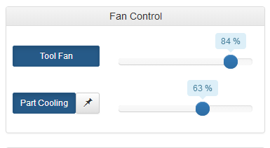
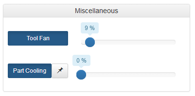
Shouldn't L255 be forcing my hotend/heatsink fan to 100% minimum speed? It keeps running at weird ranges for each print.
The fans seems to be running at 100% despite the displayed value though.
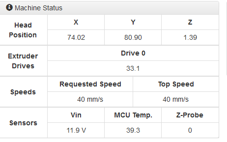
It's a genuine E3D 12v fan and I'm getting 11.9v while printing.
; Fans
M106 P1 S0 I0 F255 H-1 C"Part Cooling"      ; Set fan 0 value, PWM signal inversion and frequency. Thermostatic control is turned off
M106 P0 S1 I0 L255 F255 H1 T40 C"Hotend"    ; Set fan 1 value, PWM signal inversion and frequency. Thermostatic control is turned on


What are you trying to achieve by retracting the nozzle? Interesting idea but I can't see the purpose.
Yes, my board is rev 1.04b.
So i still need to add a 10k resistor regardless of whatever that is in the diagram?
I'm converting one of my Printrbots to a Duet 2 wifi and the last thing to do is the Z probe.
I've read through the docs and want to clarify some things so I don't fry another board like I did last year.
My probe is a PNP LJ12A3-4-Z/BY, the diagram shows what I think is a resistor between the GND and signal wire. Is this an inbuilt pull up resistor or do I still need to add one if I go for the second option described?

Ok so I ran G29 another 5 times with the bed and hotend off and still got an incrementing error as before.
Changed the probing speed to F100 as suggested and this has solved the problem, have also changed to P25 from P10 in the G31 line.
Thanks for your help.
New lines:
M558 P9 H3 F100 T6000    ; Set Z Probe to type Switch or Digital output where Z probe connector is used.
G31 X20 Y0 Z1.35 P25     ; Set Z probe trigger value, offset and trigger height
Hi dc42,
Thanks for the reply, yes I can confirm I ran nothing but G29 in between each one, the last one I ran M561 and then G29.
My hotend was at 215c and bed at 50c at each one, I'm wondering if my new probe is too close to the hotend and the cause is EMI. I've read some vague mentions of this from a few google results.
I will test again tomorrow night with a cold hotend and report back.
I have just installed a 3DTouch sensor and am having trouble getting G29 to work properly.
Each time i run G29, it seams to increment the bed height. The first 5 images are back to back bed mesh compensations without printing or touching anything. After the 5th one I issued M561 to clear the data and ran G29 again with the attached result (image 6)
All below result are from the bed at 50c and hotend at 215c, 3DTouch sensor.
Firmware is 2.02RC4(RTOS) (2018-11-18b5)
Any Ideas?
First G29

Second G29

Third G29

Fourth G29

Fifth G29

M561 and then G29

Config.g
; Configuration file for Duet WiFi (firmware version 1.20 or newer)
; General preferences

G90				; Send absolute coordinates...
M83				; ...but relative extruder moves
M667 S1				; Select CoreXY mode

; Network
M550 PLinBot				; Set machine name
M552 S1					; Enable network
M587 S"ASUS" P"Fe7awrEpMade2race"	; Configure access point. You can delete this line once connected
M586 P0 S1				; Enable HTTP
M586 P1 S0				; Disable FTP
M586 P2 S0				; Disable Telnet

; Drives
M569 P0 S1				; Drive 0 goes forwards
M569 P1 S1				; Drive 1 goes forwards
M569 P2 S1				; Drive 2 goes forwards
M569 P3 S1				; Drive 3 goes forwards
M350 X16 Y16 Z16 E16 I1			; Configure microstepping with interpolation
M92 X80 Y80 Z2395 E849			; Set steps per mm
M566 X900 Y900 Z100 E120		; Set maximum instantaneous speed changes (mm/min)
M203 X12000 Y12000 Z800 E1200		; Set maximum speeds (mm/min)
M201 X800 Y5800 Z100 E250		; Set accelerations (mm/s^2)
M906 X1500 Y1500 Z800 E1000 I30		; Set motor currents (mA) and motor idle factor in per cent
M84 S30					; Set idle timeout
M574 X1 Y2 S1				; set endstops to use motor stall

; Axis Limits
M208 X2 Y0 Z0 S1			; Set axis minima
M208 X370 Y285 Z305 S0			; Set axis maxima

; Endstops
M574 Z1 S0				; Set active low endstops

; Z-Probe
M558 P9 H10 F3000 T1000			; Set Z Probe to type Switch or Digital output where Z probe connector
is used. Used for z only.
M574 Z1 S2				; Use zprobe and home to Z Min.
G31 X20 Y0 Z0.95 P10			; Set Z probe trigger value, offset and trigger height
M557 X30:330 Y0:250 S50			; Define mesh grid

; Heaters
M307 H3 A-1 C-1 D-1			; Disable Heater 7 to use the pin for BLtouch
M307 H0 B0 S1.00			; Disable bang-bang mode for the bed heater and set PWM limit
M305 P0 T100000 B4138 C0 R4700		; Set thermistor + ADC parameters for heater 0
M143 H0 S120				; Set temperature limit for heater 0 to 120C
M305 P1 T100000 B4138 C0 R4700		; Set thermistor + ADC parameters for heater 1
M143 H1 S300				; Set temperature limit for heater 1 to 300C

; Fans
M106 P0 S0 I0 F100			; Set fan 0 value, PWM signal inversion and frequency. Thermostatic control is turned off
M106 P1 S1 I0 F250 H1 T40		; Set fan 1 value, PWM signal inversion and frequency. Thermostatic control is turned on
M106 P2 S0.5 I0 F250 H1 T45		; Set fan 2 value, PWM signal inversion and frequency. Thermostatic control is turned on

; Tools
M563 P0 D0 H1 F0			; Define tool 0
G10 P0 X0 Y0 Z0				; Set tool 0 axis offsets
G10 P0 R0 S0				; Set initial tool 0 active and standby temperatures to 0C
M501					; read stored parameters
I did infact have M106 P1 S255 in my starting gcode which is now removed. Nothing in ending script or start.g/stop.g
Removing it from my starting script solved the problem, Thanks mate!
I have set fan 1 to thermostatic control with M106 and it turns on when the hot end reaches 45c and the Fan 1 speed slider disappears from the machine control tab but after a print completes it doesn't switch off when the temp goes below 45c again. The fan speed slider is also returned after a 5hr print so I can manually switch it off.
But If I turn the fan off with the fan 1 slider and then start another print shortly after, the fan doesn't turn on when the temp is reached.
Gcode used to switch it back on: M106 P1 T45 H1
Gcode from config.h:
; Fans
M106 P0 S0.3 I0 F500 H1 T40 ; Set fan 0 value, PWM signal inversion and frequency. Thermostatic control is turned off
M106 P1 S0.5 I0 F500 H1 T45 ; Set fan 1 value, PWM signal inversion and frequency. Thermostatic control is turned on
M106 P2 S0.5 I0 F500 H1 T45 ; Set fan 2 value, PWM signal inversion and frequency. Thermostatic control is turned on
@hevilp can you upload the. csv file for both g29 and g32?
I just gave it a quick test and can confirm this has made a substantial improvement. I'm currently in the middle of moving house but will definitely spend some more time testing when I can. There are a few other improvements to be made when I get the time. Compression when tapping lightly is actually much less than 0.2mm, I would say 0.05-0.1mm depending on how tight the screws are.
Do you have another printer you can use to reprint the lower orion mount? I have made some changes to it which I believe will improve repeatability and mechanical reliability.
I haven't a chance to test properly but if you want to give it a shot, you are welcome to.
I'm using red 40-A-L o-rings on the bottom of the piezo, with about 20% compression by tightening the 4x mounting screws. I've modified the mount so that the o-ring compression is enough to keep the hotend steady but the contact on the peizo is much lighter than before.
Reduced the height and diameter of those bosses so they only located the o-rings.

Reduced the height of the center ring to match about 20% compression on the o-rings.

Tighten evenly until the centre ring is touching the piezo. You should still have a rigid mount but with 0.2-0.5mm compression when tapping.

Here is the .stl, make sure you print in 0.1mm layer height or similar.
0_1537990342746_PiezoOrionRemix.stl
These are the o-rings:
I will hopefully be able to spend some time testing it in the next few weeks but for now if anyone is able to share their thoughts that would be very helpful.
I stopped using my orion after having simular problems. During tests it worked very well and was accurate and repeatable but during printing there was too much play in the mount causing wobble of the hotend.
Increasing preload on the peizo made the hotend sort of rigid enough but made the peizo far less responsive and reliable. It seems you need the perfect balance of preload on the screws but after 3 weeks of fiddling, loctite and reassembling I could not get satisfactory results from it.
I may give it another chance in the future but I think it will need some epdm or foam grommets on each screw to reduce wobble and a slight redesign of the mount.
Update:
I spent way to long thinking I was more stupid than I am trying to get this to work.
Ordered another sensor, exact same model number and it works perfectly. I think I might be using the wrong diode though because it reads 715 when triggered instead of 1000 but it still seams to work so I'm happy.
Thanks for everybodys patience. 
I have read the wiki countless times. I should be able to plug it straight in with a reversed diode on the signal wire for protection.
I don't know why sigxcpu suggest I install a pull-up resistor, I don't know what an open collector is but I have read through the link he/she posted and am still none the wiser but am willing to try anything.
I have the new NPN sensor wired up currently as per the wiki and my image below.
With the Z_PROBE_IN disconnected, The LED is on when not sensing and turns off when near a metallic object. Indicating I have a NC sensor.
with the Z_PROBE_IN connected, The LED is on regardless of it sensing or not, It dims very slightly when near a metallic object. The duet does not sense a change when using M558 P1 or P4

Thanks,
So I read through that page and measured the resistance between each wire.
results in the image below, If I use the 10k value as R1, should I be wiring it up like the bottom diagram?
