Delta arm length
-
I don't see settings for carriage or effector offsets. The rod angles, delta radius, and printable radius are dependent on them. The delta height is dependent on the effector rod center to nozzle tip z height and z height at limit switch engagement.
With 500mm horizontal extrusions and robot digg 2040 corners I've got to set the rod length to 384 to get 60 degree rod angle at center which isn't likely unless the offsets are large?
-
Effector offset (both horizontal and vertical) is correctly calculated for a Duet Smart Effector.
Carriage offset is (currently) a fixed assumption. It takes quite a bit of change here to have any real effect. I can add a setting for it... it may take a day or two. If you want it faster than that, use your browser debugger to save the JavaScript to your local drive. All offsets and assumptions are abstracted into variables (with comments) at the very top of the script. All measurements are MM
Here are the current settings:
// Carriages Mag Ball offsets var DELTA_CARRIAGE_ADAPTOR_TOWER_RADIUS_to_BALL = 35; var DELTA_CARRIAGE_ADAPTOR_BALL_to_BALL = 55; var DELTA_CARRIAGE_ADAPTOR_ENDSTOP_to_BALL_OFFSET_TOP = 20; // From the center of the line through the balls, to the tip of the bolt that hits the upper endstop. var DELTA_CARRIAGE_ADAPTOR_ENDSTOP_to_BALL_OFFSET_BOT = -40; // From the center of the line through the balls, to the part of the carriage that hits the lower endstop. -
Yep, that could make quite the difference. My carriage + effector offsets are 64.1mm and your presets combine to 90mm.
-
And our measuring point of carriage offset could be different. I'm measuring from center of pivot point to center of truck wheels which ride in the innermost v of the 2040 extrusion. Without smooth rods it is probably best to define it in delta radius and effector offset or define what point carriage offset is measured to on the vertical exrusions.
-
At the carriage, it is measured from the center of the ball to the geometric center of the vertical extrusion. Everything in the whole model is measured to geometric centers of whatever... so I'm not going to change this.
Note that it is "defacto standard" to specify diagonal-arm-length ball-center to ball-center (not the "rim of cup to rim of cup" that you'd measure on the physical rod). Every manufacturer of which I'm aware labels their rods this way.
Specifically, the current hard-coded value is DELTA_CARRIAGE_ADAPTOR_TOWER_RADIUS_to_BALL = 35; this is the total from cener of ball to center of 2040. So about 15 "inward" from the "face" of the 2040.
Of course, this depends on Smooth Rod vs. Wheels in the 2040 slots vs. Linear Slides, AND the exact layout of the carriages themselves. 35 was "hard coded" for an average carriage that allows for a belt, regardless of what else is involved.
-
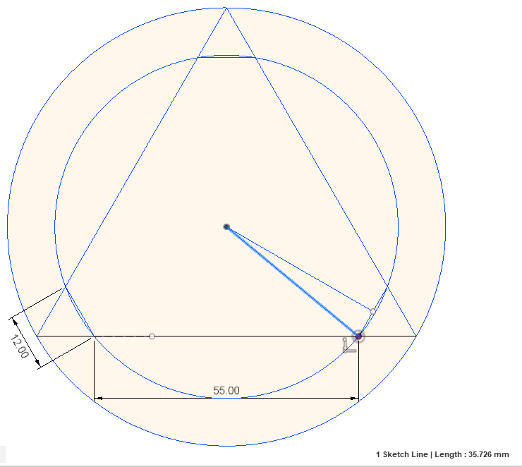
And, if you look at the code that calculates the offset for the balls on the Smart Effector, be aware that the code is calculating the offset to the 55mm long line shown here:

The Duet engineering drawing (shown above) give that 55m and 12mm dimension and never give any circle radii. The code calculates the "radius" to the 55mm line in the headers, and much later "spreads" the balls out 55/2 "along" by a distance of 55/2 to come up with the actual x/y when positioning effector, rods, etc. This is much simpler than calculating the actual circle, and then essentially reversing those calculations to "place" the balls.
The actual radius of the circle from the center of the effector to the center of the balls (i.e. an "offset" in common usage of that term) is 35.726mm. There are several ways to calculate this, all of them somewhat complex, so I just cheated and drew it in Fusion 360:

-
So, my actual offsets to the "face" of the 2040 are about 15+36= 51. To the "rail" where wheels would run, about 8 more mm or 69. Either one fairly close to your 64.1.
Nowhere near 90...
-
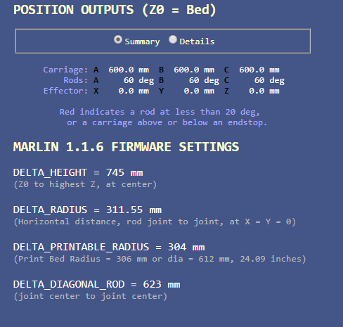
If I remember right from a long time ago in school, regardless of offsets in the below screen shot with the arms at 60 degrees isn't the hypotenuse (delta arm length) supposed to be 2 X the adjacent (delta radius) for a right triangle?

-
@alexander-mundy said in Delta arm length:
If I remember right from a long time ago in school, regardless of offsets in the below screen shot with the arms at 60 degrees isn't the hypotenuse (delta arm length) supposed to be 2 X the adjacent (delta radius) for a right triangle?
Why, yes, it should be! Let me take a look...
Edit: Now fixed.

However, I need to look at it again, however, because I changed this:
rodAngle[balln] = 180 - Math.cos(oppositeSide / DELTA_DIAGONAL_ROD) * 180;To this:
rodAngle[balln] = Math.asin((oppositeSide * (Math.sin((Math.PI / 180) * 90)) / DELTA_DIAGONAL_ROD)) / (Math.PI / 180);Which are just different methods of calculating the same thing... and verified in a debugger that the produce identical (numeric) results, yet the second one works and the first one does not... very bizarre.
-
@Danal I am planing to build a delta printer myself and using a calculator you made, so i would want to achieve something like this http://danalspub.com/DKcalc/?he=570&ve=1700&dr=624&lr=1200 . I would use Duet's smart effector + carriage adapters and MGN12H linear rails. Would the 624mm diagonal roads be sufficient for this build or do I need to download JavaScript as you mentioned and make some changes in order to determine arms length?
-
@Unborn Sorry to tell you, but I'm afraid Danal is no longer with us. He passed away in May.
-
Always sad to see the old threads ;( and the amazing work of danal