Homeall.g fails when homing all axes
-
When i home my PNP machine from OpenPnP ( G28) it works but fails when i do it from Duet3D 6XD controller with 3.6.0 Beta-4. I usually just use a sing homeall.g file to home all axes and don't have homex.g, homey.g, etc for all axes . In the act of troubleshooting to find out what is causing this i added all the homing files for each axes but i get the same error for all axes
Attached are my Config.g plus all the homing files added to try and find out what is causing this issue. Otherwise i normally just have a single file homeall.g that homes all the axes but its also failing. i just notice it when i tried to home all the axes in Duet during some tests
; Configuration file for Duet 3 MB 6XD (firmware version 3.6) ; executed by the firmware on start-up ; generated by RepRapFirmware Configuration Tool v3.6.0 on Wed Oct 16 2024 09:51:46 GMT-0500 (Eastern Standard Time) ; General preferences G21 ; Set millimeters mode G90 ; send absolute coordinates... M83 ; ...but relative extruder moves M550 P"JABIT PNP" ; set printer name ; Wait a moment for the CAN expansion boards to start G4 S2 ; Network if {network.interfaces[0].type = "ethernet"} M552 P10.0.0.200 S1 ; enable network and set IP address M553 P255.255.255.0 ; set netmask M554 P10.0.0.1 ; set gateway else M552 S1 M586 P0 S1 ; enable HTTP M586 P1 S0 ; disable FTP M586 P2 S0 ; disable Telnet M595 P120 R5 ; motion/movement commands queue length . Default M595 P60 R10 ; VERY IMPORTANT: Both Duet & OpenPnP uses 3D Cartesian Right-Hand coordinate system. ; (1) The X-axis moves to the Right (X+) and Left (X-). Right is Positive (X+) ; (2) The Y-axis moves to the Backward (Y+) and Forward (Y-). Backward is Positive (Y+) ; (3) The Z-axis moves to the Up (Z+) and Down (Z-). Up is Positive (Z+) ; (4) The C-axis (Rotation) rotates Anti-Clockwise (C+) and Clockwise (C-). Anti-Clockwise(Counter-Clockwise) is Positive (C+) ; Drives ;Physical Drives CAN ID = 0 M569 P0.0 S0 T2.5:2.5:2.5:2.5 ; X-Axis physical drive 0.0 moves Motor Backward/Reverse(axis rotates Anti-Clockwise = S0) in order to move X-axis to the Right(X+) on CAN ID = 0 - Duet 6XD Drive 0.0 with 2.5us timings between pulses M569 P0.1 S1 T2.5:2.5:2.5:2.5 ; Y-Axis physical drive 0.1 moves Motor Forward(axis rotates Clockwise = S1) in order to move Y-Axis Backward(Y+) on CAN ID = 0 - Duet 6XD Drive 0.1 with 2.5us timings between pulses ;Physical Drives CAN ID = 1 = All Shared Z Axes (Z, U, V ) each with a single Stepper Motor M569 P1.0 S1 ; Z1 & Z2 (Z = axis rotates Clockwise (S1 ) ) Axis physical drive 1.0 Rotates Motor Clockwise (Z1- & Z2+) or Anticlockwise/Reverse (Z1+ & Z2-) to move CAM driven dual nozzles down and up on Z axis on CAN ID = 1 - Duet 3HC Drive 1.0 M569 P1.1 S1 ; Z3 & Z4 (U = axis rotates Clockwise (S1 ) ) Axis physical drive 1.1 Rotates Motor Clockwise (Z3- & Z4+) or Anticlockwise/Reverse (Z3+ & Z4-) to move CAM driven dual nozzles down and up on U axis on CAN ID = 1 - Duet 3HC Drive 1.1 M569 P1.2 S1 ; Z5 & Z6 (V = axis rotates Clockwise (S1 ) ) Axis physical drive 1.2 Rotates Motor Clockwise (Z5- & Z6+) or Anticlockwise/Reverse (Z5+ & Z6-) to move CAM driven dual nozzles down and up on V axis on CAN ID = 1 - Duet 3HC Drive 1.2 ;Physical Drives CAN ID = 2 = C Axes ( W, A, B ) M569 P2.0 S0 ; C1 (W = axis rotates Anti-Clockwise/Reverse = S0) Axis physical drive 2.0 Rotates Motor Clockwise (W-) and Counter-Clockwise/Reverse (W+) on CAN ID = 2 - Duet 3HC Drive 2.0 - C 360°-continuous, but linear feed-rate M569 P2.1 S0 ; C2 (A = axis rotates Anti-Clockwise/Reverse = S0) Axis physical drive 2.0 Rotates Motor Clockwise (A-) and Counter-Clockwise/Reverse (A+) on CAN ID = 2 - Duet 3HC Drive 2.1 - C 360°-continuous, but linear feed-rate M569 P2.2 S0 ; C3 (B = axis rotates Anti-Clockwise/Reverse = S0) Axis physical drive 2.0 Rotates Motor Clockwise (B-) and Counter-Clockwise/Reverse (B+) on CAN ID = 2 - Duet 3HC Drive 2.2 - C 360°-continuous, but linear feed-rate ;Physical Drives CAN ID = 3 = C Axes (C, D, 'g) M569 P3.0 S0 ; C4 (C = axis rotates Anti-Clockwise/Reverse = S0) Axis physical drive 2.0 Rotates Motor Clockwise (C-) and Counter-Clockwise/Reverse (C+) on CAN ID = 3 - Duet 3HC Drive 3.0 - C 360°-continuous, but linear feed-rate M569 P3.1 S0 ; C5 (D = axis rotates Anti-Clockwise/Reverse = S0) Axis physical drive 2.0 Rotates Motor Clockwise (D-) and Counter-Clockwise/Reverse (D+) on CAN ID = 3 - Duet 3HC Drive 3.1 - C 360°-continuous, but linear feed-rate M569 P3.2 S0 ; C6 ('k = axis rotates Anti-Clockwise/Reverse = S0) Axis physical drive 2.0 Rotates Motor Clockwise (k-) and Counter-Clockwise/Reverse (k+) on CAN ID = 3 - Duet 3HC Drive 3.2 - C 360°-continuous, but linear feed-rate ; Axes: XYZUVWABCD abcdefghijkl mnopqrstuvwxyz are available in RepRapFirmware 3.5 and later on Duet 3 MB6HC and MB6XD only ; Best results is to configure all Controller Axes as Linear for OpenPNP, even if they are conceptually rotational this allows OpenPnP to control feed-rates, acceleration etc ; with better precision and smooth segments transitions ; X, Y Axis NEMA 34 Stepper Motor have 10mm Pitch LeadScrew, 1.8 degress/step = 360/1.8 = 200 steps/rev, 200 KHz at 16 Microstepping= 3200 pulses/rev, 320 Steps/mm (Linear ) ; Z, U, V Axis NEMA 17 Stepper Motor have 5mm (M5 = 0.8mm Pitch(Coarse = default) or 0.5mm(Fine)) Shaft diameter No Leadscrew , 1.8 degress/step = 360/1.8 = 200 steps/rev, 200 KHz at 16 Microstepping= 3200 pulses/rev, xxx steps/mm (Linear ) ; W, A, B, C , D, 'k Axis NEMA 11 Stepper Motors 1.8 degress/step = 360/1.8 = 200 steps/rev, 200 KHz at 16 Microstepping= 3200 pulses/rev ( Rotational Axes) ; Microstepping for all motors (NEMA 34, 17, 11 ) is set to 16 steps per rev , 200 kHz, with 1.8 Degree Motor = 3200 pulses/rev and Ballscrew pitch = 10 mm/rev for X & Y ; Max Speeds Tested @3200 pulses/rev: X & Y = 2800 mm/s = 168000, with accel = 18000 mm/s^2 but use 1800 mm/s with Accel = 10000 mm/s^2 for smooth movement and later adjust accordingly ; For X & Y-axis: The external Drivers (86HSE) is set to : Maximum Speed = 1600 pulse/s , Acceleration = 6400 pulse/s^2 , Deceleration = 6400 pulse/s^2 , Microstepping = 16 microsteps = 16 x 200 KHz = 3200 pulses/rev M584 X0.0 Y0.1 Z1.0 U1.1 V1.2 W2.0 A2.1 B2.2 C3.0 D3.1 'k3.2 R0 S0 ; LIN R0 = LINEAR, R1 = ROTATION M350 Z16 U16 V16 W16 A16 B16 C16 D16 'k16 I1 ; configure microstepping with interpolation. Irrelevant for external drives X & Y (X & Y = Dip Switches 3200= SW1=ON,SW2=ON,SW3=OFF,SW4=OFF,SW5=ON,SW6=ON) M92 X320.00 Y320.00 Z8.888 U8.888 V8.888 W8.888 A8.888 B8.888 C8.888 D8.888 'k8.888 ; set Axis steps per mm(microsteps/mm = pulses/mm), 10mm/rev. (X & Y = Currently 1000 pulses/rev / 10 mm/rev = 100 pulses/mm) M208 X0:340 Y0:447 Z-90:90 U-90:90 V-90:90 W-360000:360000 A-360000:360000 B-360000:360000 C360000 D-360000:360000 'k-360000:360000 ; Set axis minimum & Maximum axis Limts M566 X2000 Y2000 Z900.0 U900 V900 W900.0 W900.0 A900.0 B900.0 C900.0 D900.0 'k900.0 P1 ; set maximum instantaneous speed changes (Duet -- mm/min) and use Jerk policy 1 (Openpnp -- Jerk -- mm/s^3) M203 X100000.00 Y100000.00 Z150000.00 U150000.00 V150000.00 W120000.00 A120000.00 B120000.00 C120000.00 D120000.00 'k120000.00 ; set maximum speeds/feedrate (Duet -- mm/min) (Openpnp -- Feedrate -- mm/min) M201 X1000.00 Y1000.00 Z4000.00 U4000.00 V4000.00 W180000.00 A180000.00 B180000.00 C180000.00 D180000.00 'k180000.00 ; set accelerations (Duet -- mm/s^2) (Openpnp -- Acceleration -- mm/s^2 ) M906 Z1360.0 U1360.0 V1360.0 W560.0 A560.0 B560.0 C560.0 D560.0 'k560.0 I100 ; set motor currents (mA) and motor idle factor in per cent(I100 = "Always 100% ON = No idle time"). This is irrelevant for external drives (X & Y ) ; M84 S30 ; Set idle timeout M564 H0 ; Sets homing, H0 allows mvmnt wo homing ; Triggers -- Two triggers, one for X and one for Y, and set them to pause the machine ; Trigger number 0 causes an emergency stop as if M112 had been received. Trigger number 1 causes the print to be paused as if M25 had been received. Any trigger number # greater than 1 causes ; the macro file sys/trigger#.g to be executed. Polling for further trigger conditions is suspended until the trigger macro file has been completed M581 T1 X Y S1 R0 ; invoke trigger 1 (pause) when an inactive-to-active edge (correct for NO switches) is detected on input 1 or input 2 at any time ; Endstops ; For X and Y Axis M574 X1 S1 P"!0.io1.in" ; configure active high endstop switch for low end on X via pin io1.in M574 Y1 S1 P"!0.io2.in" ; configure active high endstop switch for low end on Y via pin io2.in ; For Z-Axis (Shared Z,U,V) - Up/down) -- CAM Driven Dual Nozzles ( 1 Motor rotates up/down to drive 2 Nozzles ) M574 Z1 S1 P"!1.io0.in" ; configure active high endstop switch for low end on Z via pin 1.io0.in M574 Z2 S1 P"!1.io1.in" ; configure active high endstop switch for High end on Z via pin 1.io1.in M574 U1 S1 P"!1.io2.in" ; configure active high endstop switch for low end on U via pin 1.io2.in M574 U2 S1 P"!1.io3.in" ; configure active high endstop switch for High end on U via pin 1.io3.in M574 V1 S1 P"!1.io4.in" ; configure active high endstop switch for low end on V via pin 1.io4.in M574 V2 S1 P"!1.io5.in" ; configure active high endstop switch for High end on V via pin 1.io5.in ; For Rotational Axes only (W, A, B, C, D, 'G(g)) M574 W1 S1 P"!2.io3.in" ; configure active high endstop switch for low end on W via pin 2.io3.in M574 A1 S1 P"!2.io4.in" ; configure active high endstop switch for low end on A via pin 2.io4.in M574 B1 S1 P"!2.io5.in" ; configure active high endstop switch for low end on B via pin 2.io5.in M574 C1 S1 P"!3.io3.in" ; configure active high endstop switch for low end on C via pin 3.io3.in M574 D1 S1 P"!3.io4.in" ; configure active high endstop switch for low end on D via pin 3.io4.in M574 'k1 S1 P"!3.io5.in" ; configure active high endstop switch for low end on 'k via pin 3.io5.in ;***Inputs ; Integrated SMC CM85 Lingera Vacuum Generators (Negative pressure) IO pins for the Nozzles to pickup SMT parts ; Digital NPN Signal Outputs (Black wire (output 1) for direct control to switch it ON/OFF) . M950 J1 C"!0.io3.in" ; Duet 3 3HC CAN_ID 0 Port 3- VG1 - Vacuum Sensor Nozzle 1 M950 J2 C"!0.io4.in" ; Duet 3 3HC CAN_ID 0 Port 4- VG2 - Vacuum Sensor Nozzle 2 M950 J3 C"!0.io5.in" ; Duet 3 3HC CAN_ID 0 Port 5- VG3 - Vacuum Sensor Nozzle 3 M950 J4 C"!0.io6.in" ; Duet 3 3HC CAN_ID 0 Port 6- VG4 - Vacuum Sensor Nozzle 4 M950 J5 C"!0.io7.in" ; Duet 3 3HC CAN_ID 0 Port 7- VG5 - Vacuum Sensor Nozzle 5 M950 J6 C"!0.io8.in" ; Duet 3 3HC CAN_ID 0 Port 8- VG6 - Vacuum Sensor Nozzle 6 ; Sensors outputs ===> Duet3 inputs ; SMC NPN Vacuum Pressure Digital Sensors -ZSE30A-01-C-L (Not Z-Probe) - Model: ZSE30A-01-C-L has 2 Outputs OUT1 = 1 NPN output , OUT2 = 1 Analog Output (1 ~ 5V) ; Analog Signal Outputs (White wire (output 2) for reading Analog vacuum sensing and pressure values). M308 S0 P"2.io0.in" Y"linear-analog" A"VG1 Pressure" F0 B37 C-130 ; Duet 3 3HC CAN_ID 2 Port 0- Analog capable - Vacuum Sensor Nozzle 1 M308 S1 P"2.io1.in" Y"linear-analog" A"VG2 Pressure" F0 B35 C-130 ; Duet 3 3HC CAN_ID 2 Port 1- Analog capable - Vacuum Sensor Nozzle 1 M308 S2 P"2.io2.in" Y"linear-analog" A"VG3 Pressure" F0 B37 C-130 ; Duet 3 3HC CAN_ID 2 Port 2- Analog capable - Vacuum Sensor Nozzle 1 M308 S3 P"3.io0.in" Y"linear-analog" A"VG4 Pressure" F0 B35 C-130 ; Duet 3 3HC CAN_ID 2 Port 0- Analog capable - Vacuum Sensor Nozzle 1 M308 S4 P"3.io1.in" Y"linear-analog" A"VG5 Pressure" F0 B35 C-130 ; Duet 3 3HC CAN_ID 2 Port 1- Analog capable - Vacuum Sensor Nozzle 1 M308 S5 P"3.io2.in" Y"linear-analog" A"VG6 Pressure" F0 B35 C-130 ; Duet 3 3HC CAN_ID 2 Port 2- Analog capable - Vacuum Sensor Nozzle 1 ; SMC NPN Vacuum Pressure Digital Sensors -ZSE30A-01-C-L (Not Z-Probe) - Model: ZSE30A-01-C-L has 2 Outputs OUT1 = 1 NPN output , OUT2 = 1 Analog Output (1 ~ 5V) ; Digital NPN Signal Outputs (Black wire (output 1) for Direct control to switch it ON=1/OFF=0 , connect to x.iox.out ports OR ; Digital NPN Signal Outputs (Black wire (output 1) for Reading Pressure where True=ON=1=Level achieved /False=OFF=0=Below Level ,connect to x.iox.in ports M950 J7 C"!4.io0.in" ; Duet 3 3HC CAN_ID 4 Port IO0- Vacuum Sensor Nozzle 1-PSensorSMC1 M950 J8 C"!4.io1.in" ; Duet 3 3HC CAN_ID 4 Port IO1- Vacuum Sensor Nozzle 2-PSensorSMC2 M950 J9 C"!4.io2.in" ; Duet 3 3HC CAN_ID 4 Port IO2- Vacuum Sensor Nozzle 3-PSensorSMC3 M950 J10 C"!4.io3.in" ; Duet 3 3HC CAN_ID 4 Port IO3- Vacuum Sensor Nozzle 4-PSensorSMC4 M950 J11 C"!4.io4.in" ; Duet 3 3HC CAN_ID 4 Port IO4- Vacuum Sensor Nozzle 5-PSensorSMC5 M950 J12 C"!4.io5.in" ; Duet 3 3HC CAN_ID 4 Port IO5- Vacuum Sensor Nozzle 6-PSensorSMC6 ;***Outputs ; The VGs Discrete digital inputs therefore triggered with following commands to ON / OFF M950 P0 C"!0.out3" Q500 ; Duet 3 6XD (V_OUTLC1 , GND ) to Phoenix Contact 24V Relay 1 ( A1+, A2- ). Allocate OUT3 to Relay 1 M42 P0 S1 ; set 100% PWM on OUT3 out3 pin ( OFF or CLOSE VGs == X6(R1) is OFF) -- Start in a Closed VG status ;M42 P0 S0 ; set 0% PWM on OUT3 out3 pin ( ON or OPEN VGs == X6(R1) is ON) M950 P1 C"!0.out4" Q500 ; Duet 3 6XD (V_OUTLC1 , GND ) to Phoenix Contact 24V Relay 1 ( A1+, A2- ). Allocate OUT4 to Relay 2 M42 P1 S1 ; set 100% PWM on OUT3 out3 pin ( OFF or CLOSE VGs == X7(R2) is OFF) -- Start in a Closed VG status ;M42 P1 S0 ; set 0% PWM on OUT3 out3 pin ( ON or OPEN VGs == X7(R2) is ON) M950 P2 C"!0.out5" Q500 ; Duet 3 6XD (V_OUTLC1 , GND ) to Phoenix Contact 24V Relay 1 ( A1+, A2- ). Allocate OUT5 to Relay 3 M42 P2 S1 ; set 100% PWM on OUT3 out3 pin ( OFF or CLOSE VGs == X10(R3) is OFF) -- Start in a Closed VG status ;M42 P2 S0 ; set 0% PWM on OUT3 out3 pin ( ON or OPEN VGs == X10(R3) is ON) M950 P3 C"!0.out6" Q500 ; Duet 3 6XD (V_OUTLC1 , GND ) to Phoenix Contact 24V Relay 1 ( A1+, A2- ). Allocate OUT6 to Relay 4 M42 P3 S1 ; set 100% PWM on OUT3 out3 pin ( OFF or CLOSE VGs == X11(R4) is OFF) -- Start in a Closed VG status ;M42 P3 S0 ; set 0% PWM on OUT3 out3 pin ( ON or OPEN VGs == X11(R4) is ON) M950 P4 C"!0.out7" Q500 ; Duet 3 6XD (V_OUTLC1 , GND ) to Phoenix Contact 24V Relay 1 ( A1+, A2- ). Allocate OUT7 to Relay 5 M42 P4 S1 ; set 100% PWM on OUT3 out3 pin ( OFF or CLOSE VGs == X12(R5) is OFF) -- Start in a Closed VG status ;M42 P4 S0 ; set 0% PWM on OUT3 out3 pin ( ON or OPEN VGs == X12(R5) is ON) M950 P5 C"!0.out8" Q500 ; Duet 3 6XD (V_OUTLC1 , GND ) to Phoenix Contact 24V Relay 1 ( A1+, A2- ). Allocate OUT8 to Relay 6 M42 P5 S1 ; set 100% PWM on OUT3 out3 pin ( OFF or CLOSE VGs == X13(R6) is OFF) -- Start in a Closed VG status ;M42 P5 S0 ; set 0% PWM on OUT3 out3 pin ( ON or OPEN VGs == X13(R6) is ON) ;LIS3DH or LISwDW12 Accelerometer via SPI on Temp_DB connector . Use Input Shaping plugin to reduce ringing ; Default sampling rates and resolutions : LIS3DH: 1344 400 200 , LIS2DW12: 1600 800 400 200 M955 P0 C"spi.cs2+spi.cs1" ; All wires connected to temp DB connector, no temperature daughterboard. ;Collect accelerometer samples and save them to .csv file : default folder 0:/sys/accelerometer. Comment out when not collecting Accelerometer data M956 P0 S10 A0 ;MODBUS M575 P1 B115200 S7 ; Set Serial P1 comms ( IO0.in/out -Shared with PanelDue Header for UART Connection) parameters for TX and RX for the RS485 MODBUS RTU to FX3U-48MR PLC (All Comms ModBus RTU - Auxillary Serial Port 1) ;M575 P2 B115200 S7 ; Set Serial P2 comms ( IO1.in/out -Shared with RS485 Header on V1.02 and Later ) parameters for TX and RX for the RS485 MODBUS RTU to FX3U-48MR PLC (All Comms ModBus RTU - Auxillary Serial Port 2) ;M260.1 P1 A1 F{0x06} R{0x001E} B1 ; Test Modbus Write to Holding registers Corresponding to Coils on Base 1 Feeder 1 (Not Connected) ;M261.1 P1 A1 F{0x03} R{0x001E} B1 ; Test Modbus Read from Holding or Input registers / Coils on Base 1 ;M260.1 P1 A1 F{0x06} R{0x001E} B0 ; Test Modbus Write to Holding registers Corresponding to Coils on Base 1 Feeder 1 (Not Connected) ; Enable All the axes, drives and motors M17 ; Enable All Axes, and motors connected to Duet3 6XD Controller ; Heaters ; Fans ; Tools ; Custom settings are not defined G90 ; send absolute coordinates...Last Command. -
-
-
 undefined Phaedrux marked this topic as a question
-
A couple of the files for easier referencing:
homeall.g; homeall.g ; called to home all axes - Faster homing all axes in parallel ; Note: Fxxx is the FeedRate/minute of the move between the starting point and endpoint ; Enable All the drives M17 ; Enable All the drives M574 X1 S1 P"!0.io1.in" ; define X axis endstop, minimum end M574 Y1 S1 P"!0.io2.in" ; define Y axis endstop, minimum end ; Move Z, U, V to Park or Zero (Minimum) to avoid dragging or breaking the Nozzles before homing any axis G91 ; relative positioning G1 H2 Z0 U0 V0 F10000 G90 ; absolute positioning ; Home X-Axis and Y-Axis first G91 ; relative positioning G1 H2 X0 Y0 ; set axes position explicitly to Zero i.e move X and Y-axis Minimum Homing endstop and stop there G1 H2 X40 Y40 F10000 ; move quickly to X and Y axis endstops and stop there (first pass) G1 H2 X-40 Y-40 F10000 ; go back a few mm G1 H2 X0 Y0 ; move X and Y-axis Minimum Homing endstop and stop there (first pass) G90 ; absolute positioning M574 X0 M574 Y0 ; Home Shared Z-Axes first (Z, U, V,) Second Pass G91 ; relative positioning G1 H2 Z0 U0 V0 G1 H2 Z-20 U-20 V-20 F100000 ; lift Z,U,V relative to current position G1 H2 Z20 U20 V20 F100000 ; Lower Z,U,V relative to current position G1 H2 Z0 U0 V0 ; move rotational axes to Minimum Homing endstop and stop there G1 H2 Z20 U20 V20 F100000 ; Lower Z,U,V relative to current position G1 H2 Z-20 U-20 V-20 F100000 ; lift Z,U,V relative to current position G1 H2 Z0 U0 V0 ; set axes position explicitly to Zero G90 ; absolute positioning ; Home Rotational axes (W, A, B, C, D, 'k) G91 ; relative positioning G1 H2 W0 A0 B0 C0 D0 'k0 G1 H2 W180 A180 B180 C180 D180 'k180 F100000 ; Rotate all 'Rotational axes relative to current position G1 H2 W-180 A-180 B-180 C-180 D-180 'k-180 F100000 ; Rotate all 'Rotational axes up until the endstop is triggered G1 H2 W0 A0 B0 C0 D0 'k0 ; move rotational axes to Minimum Homing endstop and stop there ; Explicity set all axes to Zero ( Minimums ) G1 H2 X0 Y0 Z0 U0 V0 W0 A0 B0 C0 D0 'k0 ; set all axes position explicitly to Zero, if not already done ; G92 X0 Y0 Z0 U0 V0 W0 A0 B0 C0 D0 'k0 ; set the current user axes position where the machine is located explicitly as Zero Point (Machine Origin Point), if not already done G90 ; absolute positioningand
homex.g; homex.g ; called to home all axes - Faster homing all axes in parallel ; Note: Fxxx is the FeedRate/minute of the move between the starting point and endpoint ; Enable All the drives M17 ; Enable All the drives ; Move Z, U, V to Park or Zero (Minimum) to avoid dragging or breaking the Nozzles before homing any axis G91 ; relative positioning G1 H2 Z0 U0 V0 F10000 G90 ; absolute positioning M574 X1 S1 P"!0.io1.in" ; define X axis endstop, minimum end ; Home X-Axis and Y-Axis first G91 ; relative positioning G1 H2 X0 ; set axes position explicitly to Zero i.e move X and Y-axis Minimum Homing endstop and stop there G1 H2 X40 F10000 ; move quickly to X and Y axis endstops and stop there (first pass) G1 H2 X-40 F10000 ; go back a few mm G1 H2 X0 ; move X and Y-axis Minimum Homing endstop and stop there (first pass) G90 ; absolute positioning ; M574 X0@developeralgo222 said in Homeall.g fails when homing all axes:
When i home my PNP machine from OpenPnP ( G28) it works but fails when i do it from Duet3D 6XD controller with 3.6.0 Beta-4
So do you mean sending G28 from openPNP runs correctly, but sending G28 fro the console on DWC does not? That is extremely strange.
To debug this what you can do is try sending the commands from one of the simpler macros (e.g. homex.g) line by line from the console. I note that in homex.g you are trying to move Z, U and V axis before they are homed, also you are moving the in relative mode by 0 (i.e. they are not moving at all). Furthermore later in homex.g you are moving X in relative mode by 0 so that command is not doing what you expect it to. Some of that confusion between relative and absolute mode with 0 distance moves is also present in homeall.g
-
While this suggestion may lead to non-optimal homing of all axes I find it simpler.
I insure that each file to home one axis is working.
Then in the home all file I simply invoke each individual file with M98, in the required order.
Question: Why are you setting the endstops in your homeall.g file?
Thanks.
Frederick
-
@T3P3Tony
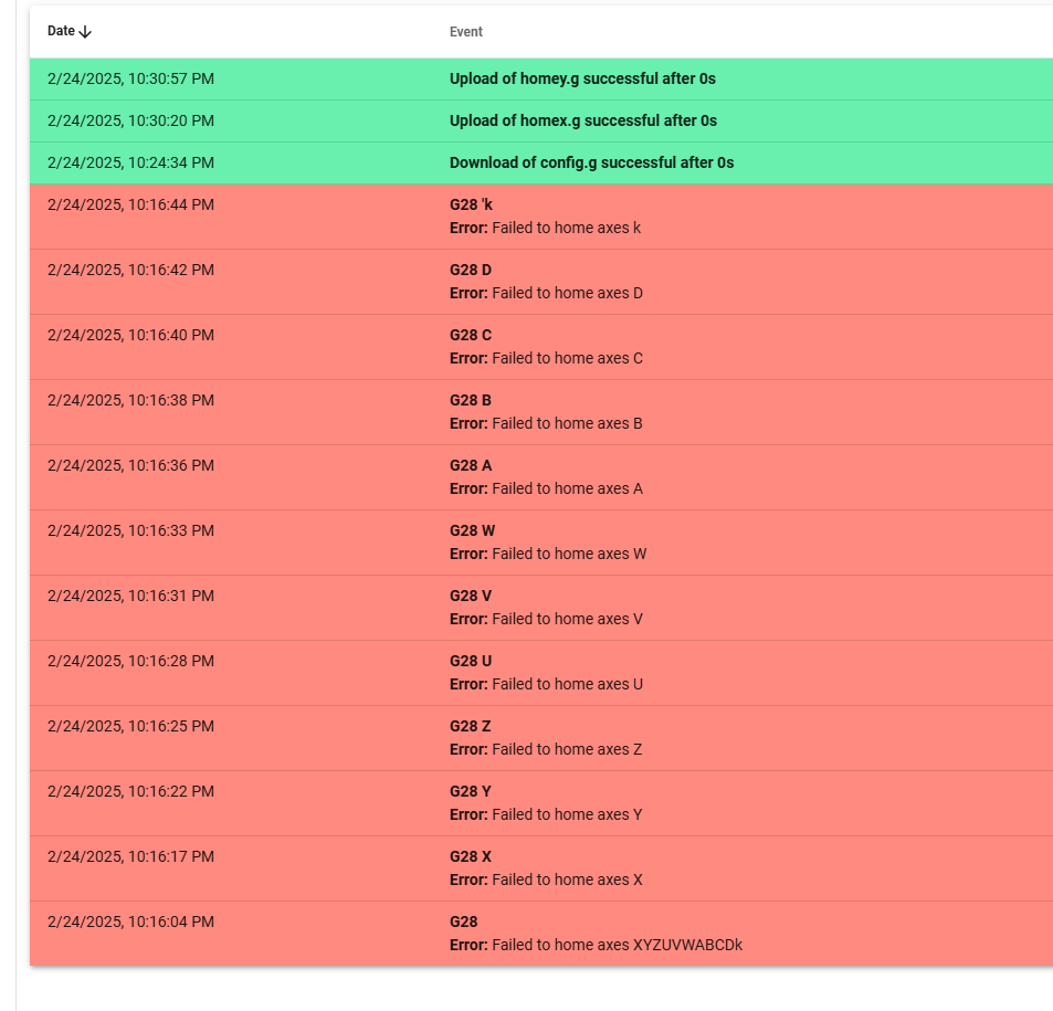
i tried to home each individual Axis on Duet3D 6XD controller and all of them failed . Then i tried homeall and it also failed .When i click on the Dashboard buttons & Home all, i get same results of failure while it actually homes the axis . it seems
From Duet3D 6XD either buttons on the Dashboard or Commands on the console throws errors of "failed to home the axis " while it actually does home it but homeall behaves differently it homes all other axis apart from X & Y
i wish Duet3D logs did have a more descriptive information on the issue and what might be causing it instead of just generic "failure" information
-
@developeralgo222 I recommend:
- Configure your endstops in config.g unless you need to remap them in your homing files (which is a more advanced requirement) - I see you are doing this.
- Focus on on one axis to start with and get it working. then move to the next one etc.
- Start with the axis that needs to move first in the homing sequence.
- Don't try to move an axis in a homing file of another axis until its homed
- Remove relative moves where you are moving an axis by 0.
- Keep the initial homing files as simple as possible to allow for homing and one that works, then extend it.
- Do homeall.g last, and as @fcwilt says, start by just calling the other homing macros in the correct order. you can rewrite homeall.g to run homing operations in parallel to save time homing once its all working.
So for example, if X can be homed first. this would be your initial homex.g:
; homex.g

; Home X-Axis
G91                     ; relative positioning
G1 H2 X-345 F10000           ; home X to Minimum Homing endstop and stop there
G1 H2 X5  F10000   ; go back a few mm
G1 H2 X-6    F1000          ; home X to Minimum Homing endstop and stop there, more slowly
G90                  ; absolute positioning
This is based on your config.g showing your X axis is 340mm long (M208 X0:340...) with the endstop on the low end (M574 X1...)
Its also based on your previous files so assumes the feed rates are suitable. Also please check your endstops are wired correctly etc before running this macro.
-
@developeralgo222
i can confirm that the issue seems to be either DWC or Duet3D Firmware because it seems to home the individual axes but you still get an error " Failed to home axes ". As i said above homeall behaves differently it only home all other axes but not X & YThis needs to be fixed. i need to configure the Accelerometer to collect Acceleration Data on X & Y for input shaping and fine tuning but i can't do that in input shaping plugin if it can't see status of the X & Y & Z as being homed.
-
To me it doesn't seem likely that the problem is in the firmware.
And, if you would be so kind, in the future please post files using the </> tag, rather than as a links.
With the </> tag the code appears right in your post and we all don't have to download files just to look at them.
Thanks.
Frederick
-
I saw another problem. you have two endstops defined in config.g for some axis but only one is supported so the second endstop command is the one that is being used. for example:
M574 Z1 S1 P"!1.io0.in"             ; configure active high endstop switch for low end on Z via pin 1.io0.in
M574 Z2 S1 P"!1.io1.in"             ; configure active high endstop switch for High end on Z via pin 1.io1.in
only the high end endstop is used.
Did you try mu modified hmex.g to see if it worked?
-
@T3P3Tony
Got major issues with endstop triggers and need your help guysi was just going through the endstops again . Here is what i have noticed.
Explanation:
(1) For X-axis i have 2 endstops (1 NEMA34 Stepper motor on the X-axis , one at 0(min) and other at 340 (max) ) but both are connected together to act as 1 single endstop. So that if the machine touches any of them it will trigger for X-axis ( 2 physical endstops acting as 1 endstop )
(2) For Y-Axis i have 4 endstops ( 1 NEMA34 Stepper motor on the Y-axis with 2 Linear rails , each Linear rail has one at 0(min) and other at 447 (max) but all 4 endstops are connected together to act as 1 single endstop. So that if the machine touches any of them it will trigger for Y-axis ( 4 physical endstops acting as 1 endstop)
(3) For Z, U, V because they are shared Z-based CAM axes .i.e Z = ( Z1, Z2 ) , U = (Z3, Z4), V = ( Z5 , Z6 ) . Each of them has its own single endstop ( 6 endstops in total)
(4) For Rotational axes W, A, B, C, D, k -- all have their own single endstop ( 6 endstops in total )
Observed trigger testing Results when covering the endstop optical lights to trigger the endstops:
NOTE: For all axes , i observed that if i moved the machine to where it should trigger the axis endstop. it shows that its triggered on the dashboard. but when i move the machine away from the endstop it does not show that its not triggered. is this normal ?
(1) For X , it only actually triggers when both 2 physical endstops are touched at the same time. This actions really opposite of what i would like , which if any of the 2 physical ends is touched it triggers
(2) For Y , it only actually triggers when all 4 physical endstops are touched at the same time. This actions really opposite of what i would like , which if any of the 4 physical ends is touched it triggers
(3) Z , U , V ( Z1, Z2, Z3, Z4, Z5, Z6 ) only Z2 , Z3, Z6 triggers Z , U , V respectively but not Z1, Z3, Z5
(4) W,A,B,C,D,k all trigger
-
@developeralgo222
NOTE: all endstop triggers seem to be acting in the Opposite wayi.e if triggered it shows OFF on Dashboard and if not triggered it shows ON (Green) on the Dashboard
According the documentation :
In DWC v3.5 and later, the endstop status is indicated in the Status panel. If the endstop is triggered, a green square will highlight the axis that is triggered. If there is no green square, it is not triggered.
in my case its exactly opposite
-
For X-axis i have 2 endstops, one at 0(min) and other at 340 (max) ) but both are connected together to act as 1 single endstop
That's a problem: Endstops are a means to determine a physical location for an axis. If you can "home" the axis to two opposite locations, having both endstops wired together (i.e. in parallel), you are lost. Best is to just keep one endstop per axis.
-
according to Duet3 Documentation :
RepRapFirmware only supports one endstop per motor per axis. If your axis only has one motor, you can only have one endstop . is this still the case ?
On X-axis & Y-axis
To try and remedy this: i am thinking of doing this
(1) For X-axis , only have 1 physical endstop at min or max
(2) For Y-axis, only have 2 physical endstops (connected in parallel) each per Y-axis rail both at min or max
NOTE: i have the 4-wire Panasonic Optical Endstops PM-U25-N ( NPN type) (Black, Blue, Brown, white ) connected to Duet3D 6XD & 3HC board IO ports as follows:
Panasonic pm-254565_e_cata.pdf
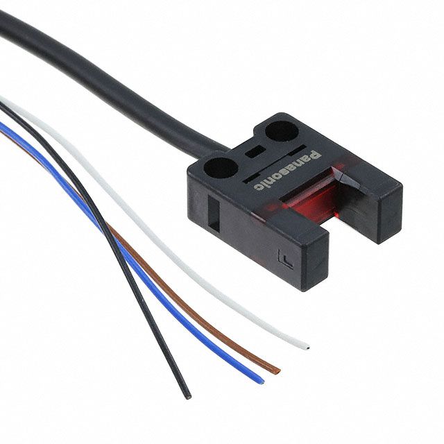
Black Wire ==> IOx.in
Blue Wire ==> GND
Brown Wire ==> 5V_EXTQuick Question: Normally what is the best location for an endstop for Duet3D 6XD boards is at Min or Max locations of the Axis ?
My triggers seem to be acting in reverse.
Trigger OFF means ON (Green on Dashboard) and Trigger ON means OFF for all axes
-
@developeralgo222 yes, that's still the case of 1 per axis.
It makes normal difference whether they are at min or max -
@developeralgo222 said in Homeall.g fails when homing all axes:
Trigger OFF means ON (Green on Dashboard) and Trigger ON means OFF for all axes
This is because the endstops are defined with the signal inverted, due to the "!", e.g.:
M574 X1 S1 P"!0.io1.in"see:
https://docs.duet3d.com/en/User_manual/Reference/Gcodes#m574-set-endstop-configurationTry
M574 X1 S1 P"0.io1.in"Its really worth following the documentation for setting up endstops:
https://docs.duet3d.com/en/User_manual/Connecting_hardware/Sensors_endstopsOnly have the endstop at one end of the axis.
Regarding this:
@developeralgo222 said in Homeall.g fails when homing all axes:
(2) For Y-axis, only have 2 physical endstops (connected in parallel) each per Y-axis rail both at min or max
However in your config.g you only have 1 motor on Y so you can only have 1 endstop:
M584 X0.0 Y0.1 Z1.0 U1.1 V1.2 W2.0 A2.1 B2.2 C3.0 D3.1 'k3.2 R0 S0 -
(1) For X-axis , only have 1 physical endstop at min or max
That's fine.
(2) For Y-axis, only have 2 physical endstops (connected in parallel) each per Y-axis rail both at min or max
Why? For each axis, you want to have one known position from where you then establish a coordinate system.
There are reasons to become confused:
- in case you have multiple steppers per axis (think of 3 motors for Z), you may want to level or tram the printbed or maybe the X plane (2 steppers). These cases are supported by RRF, but the rule: "one endtop per motor" stays valid. If your idea is to "tram" the Y axis, you need to wire one endstop per motor. In your arrangement, one or both of the endstops act as a combo, i.e. they don't provide one signal per stepper.
- as a safety measure, endstops on each end of an axis can be helpful (well, sometimes). If triggered, they can stop any motion beyond their respective positions. Technically, you can invoke a trigger (e.g. macro) to take appropriate action. That's a use case where an arrangement of endstops such as yours makes perfect sense.
- to initiate a coordinate system, you need to know one single spot per axis. This can be at any location on an axis, so the term "endstop" is somehow misleading. Many users have the idea of their "endstops" representing the origin of the printable area, but RRF allows you to define the origin to be somewhere else - for example, my X(Y origin is in the bed's center.
-
@infiniteloop said in Homeall.g fails when homing all axes:
(2) For Y-axis, only have 2 physical endstops (connected in parallel) each per Y-axis rail both at min or max
Why? For each axis, you want to have one known position from where you then establish a coordinate system.
I have 2 linear rails on Y-axis ( it moves on Dual Rail ) but only 1 Stepper Motor for controlling the Y-axis . So to comply with 1 Endstop/Motor/Axis on Duet and to remedy the Y-axis i am removing 2 endstops at the Max of the Y-axis. Just leaving 2 endstops at the Min of each rail . The 2 endstops are connected as a 1 single Endstop at the Min only. Will this work for Y-axis?
-
What is your thinking on having those two endstops?
You are aware that endstops serve no purpose except during G1 H1 or G1 H3 or G1 H4 moves?
Frederick
Printers: a small Utilmaker style, a small CoreXY and a E3D MS/TC setup. Various hotends. Using Duet 3 hardware running 3.4.6
-
@fcwilt
wasn't aware of that . So really, what's the value-added in having endstops anyway in duet ? since they seem to be integral part in some Duet's movement process. I am confused about your statement