Duet 3 mini 5+/FYSETC Big Dipper on FFCP/Flashforge Creator Pro
-
But that wasn't the solution for the problem
It did help to protect the board and it stopped to restart, but now I heard a sound of a breakdown, so I have to continue my search -
I installed the default 320w psu and now it seems to work without any extra sounds
-
So now the board is able to heat the bed and start to print
But the board shuts down after several minutes of printing
I even grounded the extruder, but that didn't help a lotI wonder what I did wrong
-
@Inlinebrother does it give you an error why?
-
@jay_s_uk Hi, sometimes it gives Vdd brownout, but most of the times just shuts down and the only way to turn it on is to turn off the power and turn it back on
-
@Inlinebrother that doesn't sound good but I still think it probably points to the PSU, especially the not coming back on until power is reset
-
@Inlinebrother Staring at your above photo for a while, I can’t quite figure out the exact meaning of all lines attached to the three leftmost contacts of the PSU, labelled L, N and GND (sorry, proper symbol for „Earth“ not available).
Three lines arrive from your AC power plug: red at L, black on N, yellow on GND. The colours do not match any convention I am familiar with, so I have no real clue.
The black wire seems to be thinner than the other two. Are you sure you didn’t swap black and yellow? Depending on you country’s AC system, such a swap could possibly work … well, somehow. In this context: is the power outlet you use protected by an earth leakage circuit breaker? Is there any one of these installed in your house? Which country are you located in?
At the PSU, GND has two additional wires attached: a yellow one with black crimp connector (to ground the metal casing), and a black line, blue connector. Where does this black line go?
Sorry for being curious - just one last question: is there, in your device, any electrical connection between GND and V- (i.e. DC negative), either intentional or by accident?
-
@infiniteloop Hi, thank you for being so interested in the case, I am pretty sure that I connected the PSU cables the way they were before upgrade, because I have a photo.
My own decision was to connect a screw of the board to the PSU ground, that is where the black cable with blue ring connector is going
I didn't intentionally connect GND and V-, although I saw some guys do that on the internet.
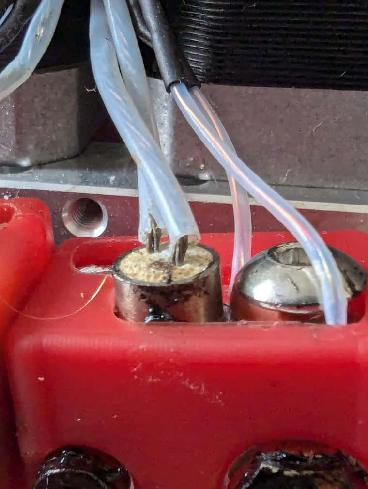
My next guess is damaged wiring of the extruder heaters, or at least exposed wiring
As far as I remember I had to get rid of insulation l, when I installed the flexion extruder, but for some reason that didn't bother me in the past
-
Also I mistakingly connected the ground to the wrong part of the extruder frame that wasn't a conductor, so connecting it the right way also might help
Update: fixing that didn't help
-
One thing that I forgot to mention, that the PSU keeps running always. It is the board that shuts down. And the led near wifi stops working together with all the fans controlled by the board, but all other LEDs are working fine
-
@Inlinebrother See our documentation on grounding here: https://docs.duet3d.com/en/User_manual/Connecting_hardware/Power_wiring#grounding
Basically:
- the incoming earth, from the power socket, should be connected to a ground point.
- parts that require grounding should connect to this ground point: PSU earth (not -V), frame, hot end and extruder metal parts, stepper motor bodies, shielded wire shielding etc.
- PSU -V should not be connected to this grounding point, and should not be bridged to earth.
Not sure what could be causing the 'Vdd brownout' other than PSU, or shorting out wiring. Maybe a failing heater?
Ian
-
@infiniteloop Hi, thanks to you and idea came to me to measure resistance with a multimeter for different connections of the PSU
And I found out that I have a direct connection (multimeter beeps) from PSU 24v to the ground when right extruder is connected to the boardAlso the resistance between the ground and PSU 24+ is about 1500 om
even without my cables attached that connect the board and the extruder to the ground
-
Ok I found an accidental connection between the right extruder pin and the ground
For some reason I was confident that nothing is touching the board. Thank you all for your ideas.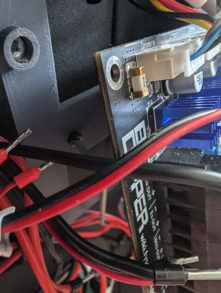
Now I measured all other connections and see that my 24v+ PSU is connected to e0, e1 and bed + and - pins
And the resistance between the - and + for the board power pins and the bed power pins is about 160 oms
Is that ok? -
I started the print, it looks promising, 25% done
Now I googled the datasheet for moons stepper motors (17HD4063-06N) that are installed on my FFCP, and as far as I understand they have a rated current of 630 mA, so I should change my config.
063 / 100 = 0.63 A for the Y axis at least
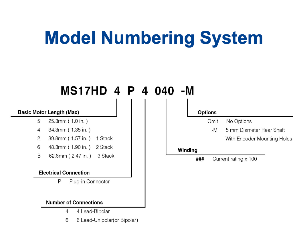
and for the extruders my FFCP has two 0.8 A rated 42HB34F08AB-22
-
I am pretty sure that I connected the PSU cables the way they were before upgrade, because I have a photo.
Sorry, I haven’t. That’s why I asked for additional information:
"Is the power outlet you use protected by an earth leakage circuit breaker? Is there any one of these installed in your house? Which country are you located in?"My own decision was to connect a screw of the board to the PSU ground, that is where the black cable with blue ring connector is going
That’s fine.
I didn't intentionally connect GND and V-, although I saw some guys do that on the internet.
Thankfully, @droftarts stepped in to clarify this one and some related topics.
I forgot to mention, that the PSU keeps running always. It is the board that shuts down.
From your photo, I can’t figure out how the board is switched off. As a side note: When electricity in your part of the world is not particularly cheap, it might be a good idea to cut power on the AC side. Thinking of safety reasons, this idea even looks better

Ok I found an accidental connection between the right extruder pin and the ground
Glad you spotted this one. Keep reporting on how it works.
Also the resistance between the ground and PSU 24+ is about 1500 om
That value alone isn’t really telling. To check if some component inadvertently bridges to GND (instead of to V-), you’d have to disconnect any and all connections. Then, check the resistance, reconnect a single component, measure again. Repeat this procedure until all connections are back in place. Well, better try to avoid this tedious process - maybe the right extruder turns out to have been the real culprit.
Now I googled the datasheet for moons stepper motors (17HD4063-06N) that are installed on my FFCP, and as far as I understand they have a rated current of 630 mA, so I should change my config.
Don’t know how the steppers are currently configured. The section Stetting motor currents in the support document Configuring stepper motors provides detailed infos - I think even more than you ever wanted to know.
-
Ok, yesterday the printer was working for hour and a half until I turned it off. The motors were about 50 degrees celsius and I guess that's why the layers shifted. The current was set to 850 ma for xy and 400 for z, and 900 for extruders
Today I changed the config but the print failed with the HardFault
m122 === Diagnostics === RepRapFirmware for Duet 3 Mini 5+ version 3.5.3 (2024-09-18 11:25:48) running on Duet 3 Mini5plus WiFi (standalone mode) Board ID: RHYS5-6J9MK-K65J0-40TK2-JRW2Z-ZLX8A Used output buffers: 3 of 40 (18 max) === RTOS === Static ram: 103368 Dynamic ram: 121908 of which 12 recycled Never used RAM 16460, free system stack 206 words Tasks: NETWORK(2,nWait 7,14.4%,217) HEAT(3,nWait 6,0.0%,325) Move(4,nWait 6,0.0%,355) CanReceiv(6,nWait 1,0.0%,939) CanSender(5,nWait 7,0.0%,336) CanClock(7,delaying,0.0%,334) TMC(4,nWait 6,1.4%,110) MAIN(1,running,83.4%,665) IDLE(0,ready,0.0%,29) AIN(4,delaying,0.8%,264), total 100.0% Owned mutexes: === Platform === Last reset 00:16:28 ago, cause: software Last software reset at 2024-10-12 09:04, reason: HardFault invState, Gcodes spinning, available RAM 13464, slot 0 Software reset code 0x4063 HFSR 0x40000000 CFSR 0x00020000 ICSR 0x00489803 BFAR 0xe000ed38 SP 0x20012008 Task NETW Freestk 482 ok Stack: 0000017d 00000002 200014e4 00000000 20032fe9 000a0f9f 00000000 600f0000 00000000 00000000 00000000 00000000 20031e34 00000800 2002c640 2002c640 00000001 2002c496 2001882c 2001ea80 00030523 00000000 00000000 00000000 200120b8 00000014 b5dd500a Error status: 0x00 MCU revision 3, ADC conversions started 741990, completed 741988, timed out 0, errs 0 MCU temperature: min 29.1, current 31.6, max 31.8 Supply voltage: min 24.0, current 24.1, max 24.1, under voltage events: 0, over voltage events: 0, power good: yes Heap OK, handles allocated/used 0/0, heap memory allocated/used/recyclable 0/0/0, gc cycles 0 Events: 0 queued, 0 completed Driver 0: standstill, SG min 38, read errors 0, write errors 1, ifcnt 36, reads 24344, writes 10, timeouts 0, DMA errors 0, CC errors 0 Driver 1: standstill, SG min 6, read errors 0, write errors 1, ifcnt 36, reads 24343, writes 10, timeouts 0, DMA errors 0, CC errors 0 Driver 2: standstill, SG min 0, read errors 0, write errors 1, ifcnt 35, reads 24343, writes 10, timeouts 0, DMA errors 0, CC errors 0 Driver 3: standstill, SG min 0, read errors 0, write errors 1, ifcnt 32, reads 24343, writes 10, timeouts 0, DMA errors 0, CC errors 0 Driver 4: standstill, SG min 0, read errors 0, write errors 1, ifcnt 32, reads 24344, writes 10, timeouts 0, DMA errors 0, CC errors 0 Driver 5: standstill, SG min 0, read errors 0, write errors 1, ifcnt 33, reads 24343, writes 10, timeouts 0, DMA errors 0, CC errors 0 Driver 6: standstill, SG min 0, read errors 0, write errors 1, ifcnt 32, reads 24343, writes 10, timeouts 0, DMA errors 0, CC errors 0 Date/time: 2024-10-12 09:20:57 Cache data hit count 1872586024 Slowest loop: 7.85ms; fastest: 0.16ms === Storage === Free file entries: 20 SD card 0 detected, interface speed: 22.5MBytes/sec SD card longest read time 1.4ms, write time 0.0ms, max retries 0 === Move === DMs created 83, segments created 0, maxWait 0ms, bed compensation in use: none, height map offset 0.000, max steps late 0, min interval 0, bad calcs 0, ebfmin 0.00, ebfmax 0.00 no step interrupt scheduled Moves shaped first try 0, on retry 0, too short 0, wrong shape 0, maybepossible 0 === DDARing 0 === Scheduled moves 0, completed 0, hiccups 0, stepErrors 0, LaErrors 0, Underruns [0, 0, 0], CDDA state -1 === DDARing 1 === Scheduled moves 0, completed 0, hiccups 0, stepErrors 0, LaErrors 0, Underruns [0, 0, 0], CDDA state -1 === Heat === Bed heaters 0 -1 -1 -1, chamber heaters -1 -1 -1 -1, ordering errs 0 === GCodes === Movement locks held by null, null HTTP is idle in state(s) 0 Telnet is idle in state(s) 0 File is idle in state(s) 0 USB is idle in state(s) 0 Aux is idle in state(s) 0 Trigger is idle in state(s) 0 Queue is idle in state(s) 0 LCD is idle in state(s) 0 SBC is idle in state(s) 0 Daemon is idle in state(s) 0 Aux2 is idle in state(s) 0 Autopause is idle in state(s) 0 File2 is idle in state(s) 0 Queue2 is idle in state(s) 0 Q0 segments left 0, axes/extruders owned 0x0000000 Code queue 0 is empty Q1 segments left 0, axes/extruders owned 0x0000000 Code queue 1 is empty === CAN === Messages queued 8900, received 0, lost 0, errs 4675536, boc 0 Longest wait 0ms for reply type 0, peak Tx sync delay 0, free buffers 26 (min 26), ts 4945/0/0 Tx timeouts 0,0,4944,0,0,3954 last cancelled message type 4514 dest 127 === Network === Slowest loop: 5.85ms; fastest: 0.00ms Responder states: MQTT(0) HTTP(0) HTTP(0) HTTP(0) HTTP(0) FTP(0) Telnet(0) HTTP sessions: 1 of 8 === WiFi === Interface state: active Module is connected to access point Failed messages: pending 0, notrdy 0, noresp 0 Firmware version 2.1.0 MAC address 08:3a:8d:eb:24:44 Module reset reason: Power up, Vcc 3.38, flash size 2097152, free heap 42932 WiFi IP address 192.168.1.69 Signal strength -48dBm, channel 7, mode 802.11n, reconnections 0 Clock register 00002001 Socket states: 0 0 0 0 0 0 0 0 m122p106 Platform 2001d138-2001e737 SbcInterface 2001e740-2001ea70 Network 2001ea80-2001eb67 GCodes 2001eb70-2001ff6f Move 20023ff8-20024d33 Heat 20025110-20025237 PrintMonitor 20025240-2002544f FansManager 20025458-200254d7 PortControl 200254e0-2002550f Display 20025518-20025533 ExpansionManager 20025540-200282f7 m122p1007 a{0x2001ea80+8} 2001ea88: 2002c420 m122p1007 a{0x2002c420+136} 2002c4a8: 20032e60 -
@Inlinebrother Hm… Looks like as soon as you happen to touch one problem, a bunch of others surface seemingly out of nowhere. You'd need an octopus to handle all of these at once - in other words: your way to approach the issues with your printer has, IMHO, some potential to be optimised. You see, from a distance, members on this forum have to rely on your reportings, we can only guess what could possibly be the root cause of a symptom you describe.
Following this long thread, I have difficulties to find a single issue being properly resolved - when I still try to wrap my head around some of your wiring issues, I’m left with open queries and … steppers. Well ok, why not steppers for lunch, today? I even figured out that eventually, these things from the moon are rated at 1.5 A, not at 630 mA. Quite a difference, but in the meantime, you have already changed the config (interestingly, none of us has any idea of what’s in there) and moved to the next problem, a hard fault. Sure, that’s a serious one and has to be dealt with, so please understand that I don’t intend to offend you.
Instead, I propose to concentrate on a single issue at a time. That’s easier said than done, but the newly reported layer shifts are a perfect candidate for a separate thread - after the PSU- and cabling issues have been resolved. I assure you that, in this forthcoming thread, the steppers as well as the config.g will be dealt with in detail. I think you perfectly understand what I mean: You already joined the appropriate thread to report your HardFault. Others may have a different view, in my eyes, thats the perfect place to go with that.
So sorry for this rant. It’s just that we are no octopussies (as a non-native speaker, I know there’s 'something' wrong with that expression, but I have no clue what exactly
 ). Regarding the power issues and related phenomenons, please keep us informed. As 3D printer enthusiasts, we are only satisfied at a point when your FFSC works as intended - we want to hear success stories.
 -
Is the power outlet you use protected by an earth leakage circuit breaker? Is there any one of these installed in your house?
I guess so
I can’t figure out how the board is switched off
It is the Flashforge Creator Pro and it has a button behind it to turn off the power that goes to the PSU
Glad you spotted this one. Keep reporting on how it works.
Now I finally can focus on configuring other params because it works fine. I had two hard faults though.
To check if some component inadvertently bridges to GND
Before I started printing I checked once again, and ground wasn't connected to other pins.
Don’t know how the steppers are currently configured. The section Stetting motor currents in the support document
Configuring stepper motors provides detailed infos - I think even more than you ever wanted to know.As fas as currents are concerned I think I'll monitor motors temperature, for now they are not even 50 degrees hot and they say that's fine
I found macros for tuning the speeds, jerk and acceleration here https://forum.duet3d.com/topic/6181/tuning-macros-menus-accel-jerk-retraction-pressure-advance
And that's what I am going to focus on now
Finishing the test print without defects
One of the main problems for me is the layer shifting for the y axis
-
Looks like as soon as you happen to touch one problem, a bunch of others surface seemingly out of nowhere
Yeah, sorry, it might look that way. But really the biggest concern was the restarts. And here is your portion of success story, after I removed the screw I am able to print.
Hard faults don't bother me too much.
Layer shifting does, so that's my next problem
I even figured out that eventually, these things from the moon are rated at 1.5 A
That's great. I wonder how you did that?
-
That's my config right now that produced the best results.
; Configuration file for RepRapFirmware on Duet 3 Mini 5+ WiFi
; executed by the firmware on start-up
;
; generated by RepRapFirmware Configuration Tool v3.5.0 on Sun Jun 02 2024 14:45:59 GMT+0300 (Moscow Standard Time)

; General
G90 ; absolute coordinates
M83 ; relative extruder moves
M550 P"Flashforge Creator Pro" ; set hostname
M911 S19.8 R22 P"M913 X0 Y0 G91 M83 G1 Z3 E-5 F1000" ; set voltage thresholds and actions to run on power loss

M122 P500 S0 ;enabled debug

; Network
M551 P"" ; set machine password
M552 S1 ; configure WiFi adapter
M586 P0 S1 ; configure HTTP

; Smart Drivers
M569 P0.0 S0 D3 ; driver 0.0 goes forwards (X axis)
M569 P0.1 S0 D3; driver 0.1 goes forwards (Y axis)
M569 P0.2 S1 D3 ; driver 0.2 goes forwards (Z axis)
M569 P0.5 S0 D3 ; driver 0.3 goes forwards (extruder 0)
M569 P0.6 S0 D3 ; driver 0.4 goes forwards (extruder 1)

; Axes
M584 X0.0 Y0.1 Z0.2 ; set axis drives mapping
M350 X16 Y16 Z16 I1 ; configure microstepping with interpolation
M906 X700 Y700 Z350
M92 X94.12 Y94.12 Z400.00 ; configure steps per mm
M208 X0:225 Y0:145 Z0:150 ; set minimum and maximum axis limits
M566 X60 Y60 Z12 ; set maximum instantaneous speed changes (mm/min)
M203 X4800 Y4800 Z300; set maximum speeds (mm/min)
M201 X120 Y120 Z80 ; set accelerations (mm/s^2)

; Extruders
M584 E0.5:0.6 ; set extruder mapping
M350 E16:16 I1 ; configure microstepping with interpolation
M906 E700:700 ; set extruder driver currents
M92 E96.2752:96.2752 ; configure steps per mm
M566 E12000:12000 ; set maximum instantaneous speed changes (mm/min)
M203 E4800:4800 ; set maximum speeds (mm/min)
M201 E1000:1000 ; set accelerations (mm/s^2)

; Kinematics
M669 K0 ; configure Cartesian kinematics

; Endstops
M574 X1 S1 P"!io2.in"                              ; configure switch-type (e.g. microswitch) endstop for high end on X via pin !io2.in
M574 Y1 S1 P"!io3.in"                              ; configure switch-type (e.g. microswitch) endstop for high end on Y via pin !io3.in
M574 Z1 S1 P"!io4.in"                              ; configure switch-type (e.g. microswitch) endstop for low end on Z via pin !io4.in

;Sensors
M308 S0 P"temp0" Y"thermistor" T100000 B4066         ; configure sensor 0 as thermistor on pin temp0
M308 S1 P"temp1" Y"thermistor" A"RE thermistor" T100000 B4981 C1.632834e-7 ; configure sensor #1
M308 S2 P"temp2" Y"thermistor" A"LE thermistor" T100000 B4981 C1.632834e-7 ; configure sensor #1

; Heaters
M950 H0 C"out0" T0                                 ; create bed heater output on out0 and map it to sensor 0
M307 H0 R0.290 K0.260:0.000 D1.86 E1.35 S0.85 B0
M140 H0                                            ; map heated bed to heater 0
M143 H0 S120                                       ; set temperature limit for heater 0 to 120C

M950 H1 C"out1" T1                                 ; create nozzle heater output on out1 and map it to sensor 1
M307 H1 B0 S1.00                                   ; disable bang-bang mode for heater  and set PWM limit
M143 H1 S280                                       ; set temperature limit for heater 1 to 280C

M950 H2 C"out2" T2                                 ; create nozzle heater output on out2 and map it to sensor 2
M307 H2 R1.920 K0.483:0.000 D5.98 E1.35 S1.00 B0
M143 H2 S280                                       ; set temperature limit for heater 2 to 280C

; Heated beds
M140 P0 H0 ; configure heated bed #0

; Fans
M950 F0 C"out6" ; create fan #0
M106 P0 C"Board Fan" S1 L0 X1 B0.1 ; configure fan #0
M950 F1 C"out4" ; create fan #1
M106 P1 C"Extruder 0 Fan" S1 B0.1 H1 T45 ; configure fan #1
M950 F2 C"out3" ; create fan #2
M106 P2 C"Extruder 1 Fan" S1 B0.1 H2 T45 ; configure fan #2
M950 F3 C"out5" ; create fan #3
M106 P3 C"Cooling Fan" S0 L0 X1 B0.1 ; configure fan #3

; Tools
M563 P0 S"EXTRUDER RIGHT" D0 H1 F0                 ; define tool 0
G10 P0 X-34.04514634972721 Y0.29743029572304586 Z0 ; set tool 1 axis offsets
G10 P0 R0 S0                                       ; set initial tool 0 active and standby temperatures to 0C
M563 P1 S"EXTRUDER LEFT" D1 H2 F0                  ; define tool 1
G10 P1 X0 Y0 Z0                                    ; set tool 0 axis offsets
G10 P1 R0 S0                                       ; set initial tool 1 active and standby temperatures to 0C
At these jerk and acceleration for axes I have no layer shifting. There are some underextrusions though
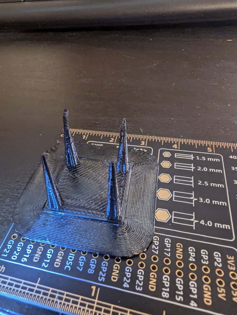
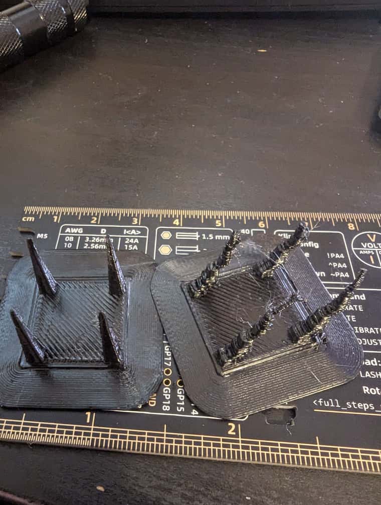
Slicer: Cura
layer size: 0.3