M42 seemingly not working on my Duet 6HC Mainboard
-
Hey all,
First some Information: I am using a Duet 3 6HC (v1.02) mainboard (with two Duet 3 1HCL expansion boards, which work perfectly fine). I am trying to use the Duet 3 "out4" and "out5" pins to drive a small voice coil motor (with the adequate motor driver in between). Therefore, I need to set the PWM Pins to 3-4 V.
What I did so far:
Configure the pins in the config.g (M950 P10 C"out4", M950 P11 C"out5"). The Pin numbers are unique and not used otherwise.Sending M42 P10 S0.5
Sending M42 P11 S0.5I tried to measure the voltages according to the docs, however, I get the following results (the jumper is set to 12V):
(https://docs.duet3d.com/duet_boards/duet_3_mb6hc/duet3_mb_6hc_v1.02_d1.1_wiring.png)GND --> V_OUTLC1 : 12V
GND --> out4.tach : 3.3V
GND --> out4: 40-60 mV
V_OUTLC1 --> out4.tach: 7.5VIf I use the same procedure with the out3, I can precisely adjust the voltage with the M42 command.
I am happy for any feedback on possible error tracking/fixing!
-
@StefanSch said in M42 seemingly not working on my Duet 6HC Mainboard:
GND --> V_OUTLC1 : 12V
That's as expected
GND --> out4.tach : 3.3V
That's as expected - there's a pull-up to 3.3V on the tacho pins (R83, R87 and R88 on the schematic I have to hand)
GND --> out4: 40-60 mV
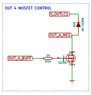
In the absence of an applied pullup, that's expected. The out pin is switched between Gnd and floating. If you don't apply any voltage it will be at a low voltage. (There's some tiny reverse leakage through a back-EMF / flyback protection diode, but that's all).

V_OUTLC1 --> out4.tach: 7.5V
Should be a little higher, but I wouldn't worry about it.
If I use the same procedure with the out3, I can precisely adjust the voltage with the M42 command.
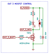
Out 3 has an LED that will pass current through even when there is no applied external load / device, so out_3 has a built-in pullup.

That is, with nothing connected and no driven command, out_4_neg will tend to sit at near Gnd. Driving it will make it switch between near-Gnd and Gnd, so it shows on a multimeter as near-Gnd
With nothing connected and no driven command out_3_neg will sit at V_Fused. Driving it will make it switch between V_Fused and Gnd, which averages on a multimeter so you see an analogue voltage.
-
@achrn Thanks for the reply!
So I attached an LED between GND and out4 (with the corresponding serial resistor of around 220 ohm).
If I connect the LED between GND and V_OUTLC1 it lights up brightly and everything is fine. If I remove the pin from the V_OUTLC1 and connect it to out4 I cannot make the LED light up, no matter what S value I use for the M42 command. The LED is still working, so that is not the issue.
I also tried to leave the LED connected between GND and V_OUTLC1, but out out4 -->GND still sits near ground.Maybe I get something fundamentally wrong, but maybe you could give me some more guidance on how to apply a positive voltage to an external pin.
-
@StefanSch I think you are fundamentally misunderstanding how the switching one the board out pins works. It's low side switching.
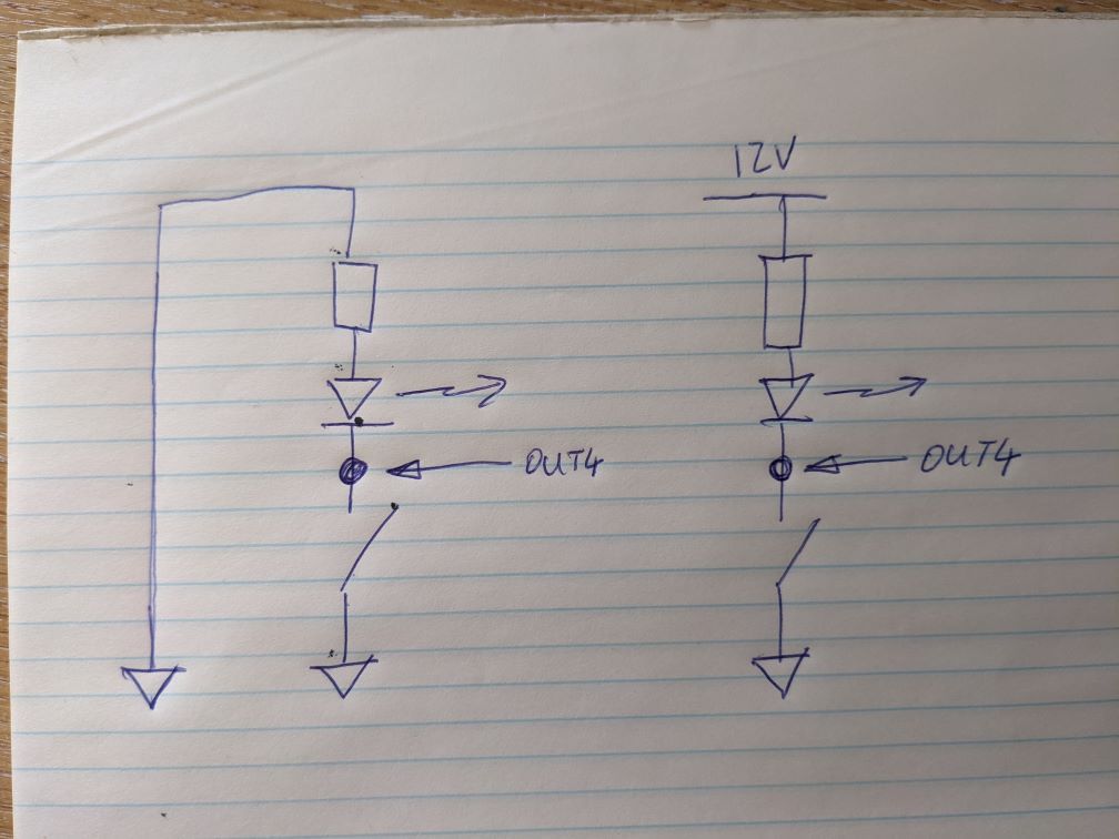
Effectively there's a switch between the out pin and ground. The board either connects out4 to Gnd, or has it connected to nothing. So if you connect an LED between out4 and Gnd, the LED never has any voltage across it - it's either connected to Gnd on both sides, or it's connected to Gnd on one side and nothing on the other side. To control the LED you need to connect the LED&resistor between 12V (or whatever volt) and out4. Then, with the 'switch' open one side of the LED&resistor is at 12V and the other side is disconnected, so no current, so no light, but when the switch is closed one side of the LED&resistor is at 12V and the other is at Gnd, so current flows, so there is light.
The board never puts voltage on Out4 - it puts Gnd on Out4.
You've created the 'circuit' on the left - there is no positive voltage in this circuit and no current flow, regardless of what the switch does. To control the LED you want to achieve the circuit on the right:

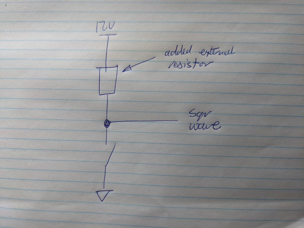
When you are trying to generate the square wave control signal, you will need to connect Out4 to a positive supply via a resistor and then take the signal from Out4. That is, you're aiming for this. When the switch is open the output will be 12V and when it's shut it will be 0V. Note this gives you a 12V square wave, which might not be what you want.

Also, since Out1-3 have have their protection diode to one voltage (V_fused) and Out4-6 are to a possibly different voltage (V_outlc1) and Out7-9 are to another possibly different voltage (V_outlc2) if you want two square waves you should probably take them both from within the same set of three. You could take them from the any of out4-9 if you have both out jumpers set the same. I wouldn't take one from 1-3 and one from 4-9 because of the different drive circuits (which as you've seen, cause different behaviour - it will just complicate matters).
-
@achrn
Perfect, thank you for the detailed explanation! Really helped me to fix my issue.