Duet Accelerometer not found on duet3 mini 5+
-
So i just got my Duet Accelerometer(new) installed on my ender 5+ with a 3 mini 5+.
But after the hole evening trying and reading and measuring im a bit lost.M955 P0 C"spi.cs2+spi.cs1" I14 q500000 Error: M955: Accelerometer not found on specified portSo summarize what i did;
ive read:
https://docs.duet3d.com/en/Duet3D_hardware/Accessories/Duet3D_Accelerometer
https://docs.duet3d.com/User_manual/Connecting_hardware/Sensors_Accelerometer
https://docs.duet3d.com/User_manual/Reference/Gcodes#m955-configure-accelerometer
Uses this wiring diagram
https://docs.duet3d.com/duet_boards/duet_3_mini_5_plus/duet3_mini5+_v0.5-v1.02_d1.5_wiring.pngAnd did this
- Installed the hardware
- Ive used the supplied 10 28awg pre connected cable .
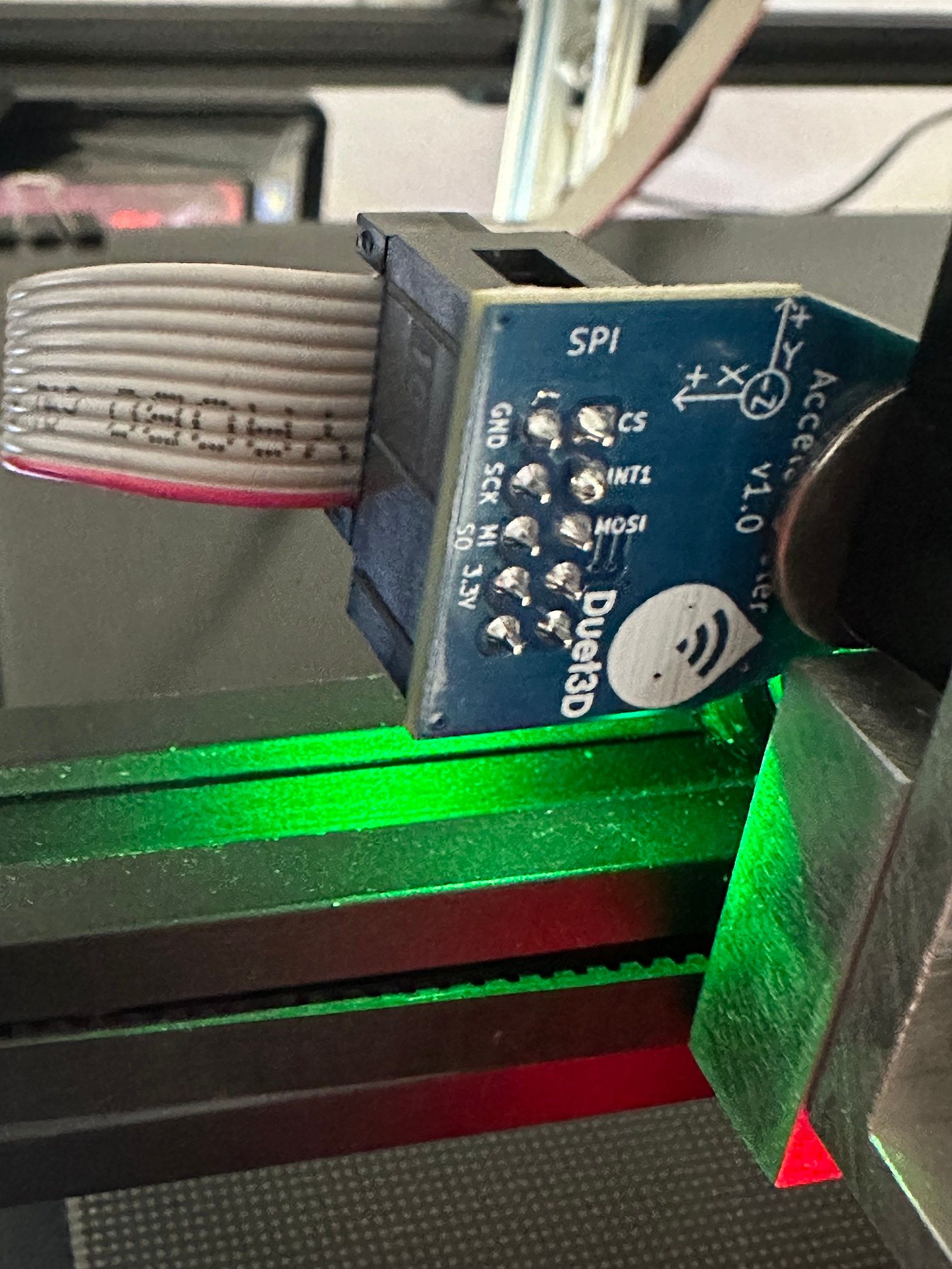
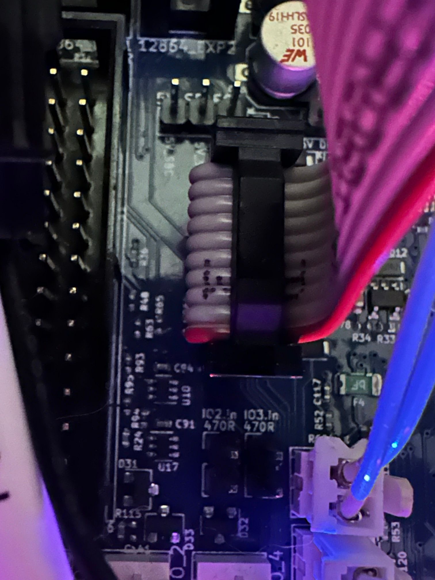
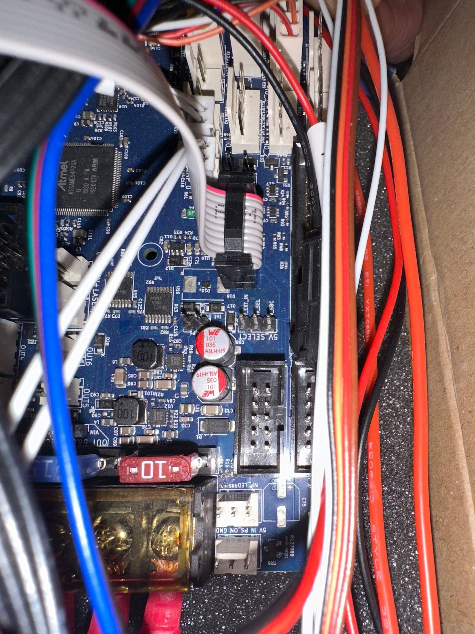
- Connected it to the de SP1 daughterboard connection
- Checked connections and cables
*Put in config;
M955 P0 C"spi.cs2+spi.cs1" I14 q500000- Ive added the Q later because of my reading, but i cant seem to find it.
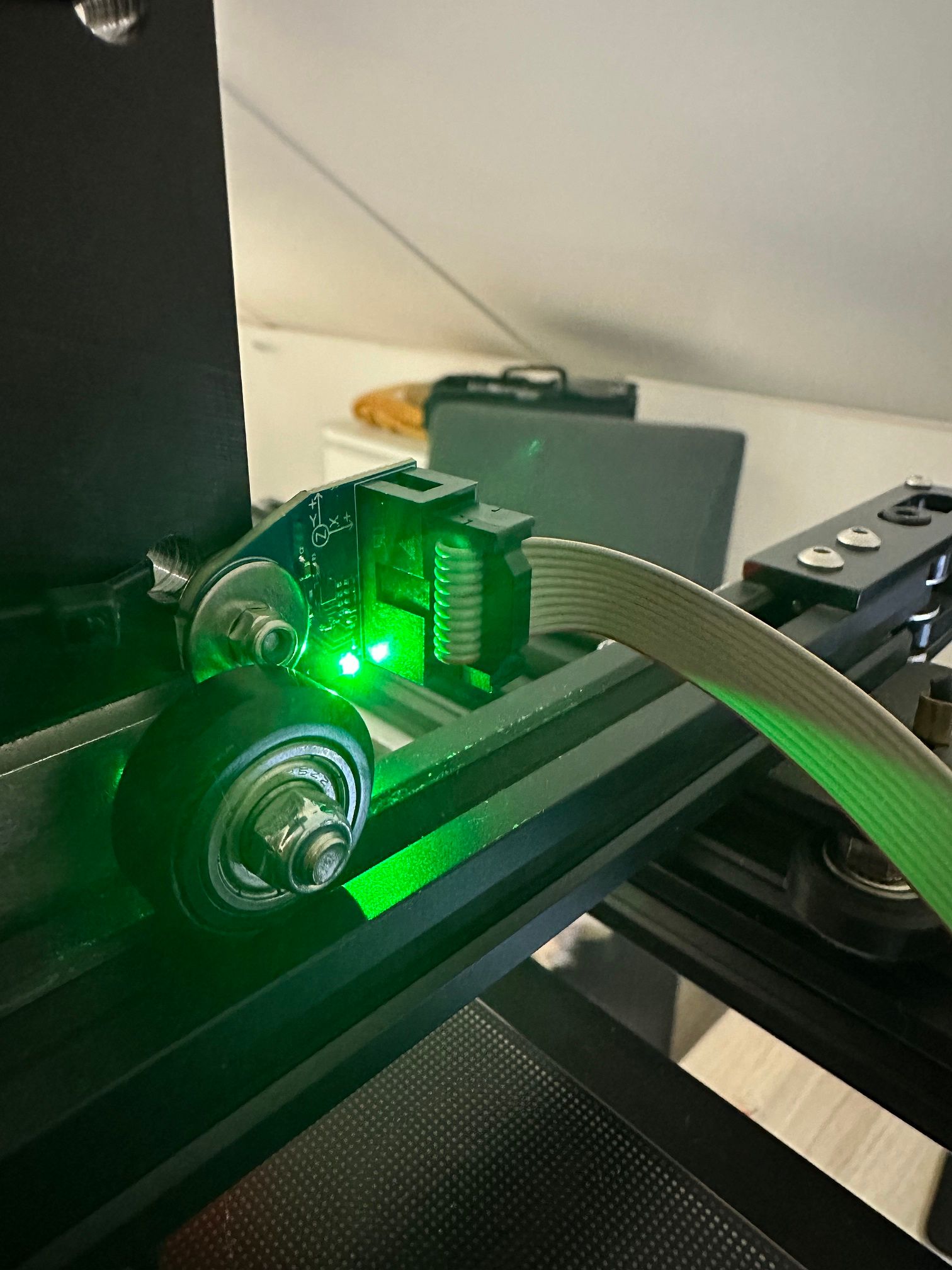
- I do have 3.3V on the accelerometer and the green LED is burning.
- double checked the wiring, and i rather not cut my wiring because i intent to use it for my Paneldue i7 relocation when im done with input shaping.
I assume the supplied cable (1meter?) is good enough the make it work? Or do i need to go MacGyver and add resistors/thin film etc?
Some pictures;


and i added config and m115 command for firmware;
m115
FIRMWARE_NAME: RepRapFirmware for Duet 3 Mini 5+ FIRMWARE_VERSION: 3.5.0-beta.4 ELECTRONICS: Duet 3 Mini5plus Ethernet FIRMWARE_DATE: 2023-06-08 23:40:14
; Configuration file for Duet 3 Mini 5+ (firmware version 3.3) ; executed by the firmware on start-up ; ; generated by RepRapFirmware Configuration Tool v3.3.16 on Wed Dec 13 2023 21:57:46 GMT+0100 (Midden-Europese standaardtijd) ; General preferences M575 P1 S1 B57600 ; enable support for PanelDue G90 ; send absolute coordinates... M83 ; ...but relative extruder moves M550 P"Ender 5 Plus" ; set printer name ; Network M552 P192.168.178.96 S1 ; enable network and set IP address M553 P255.255.255.0 ; set netmask M554 P192.168.178.1 ; set gateway M586 P0 S1 ; enable HTTP M586 P1 S0 ; disable FTP M586 P2 S0 ; disable Telnet ; Drives M569 P0.0 S0 ; physical drive 0.0 goes backwards M569 P0.1 S0 ; physical drive 0.1 goes backwards M569 P0.2 S0 ; physical drive 0.2 goes backwards (Z Axis Left) M569 P0.3 S0 ; physical drive 0.3 goes backwards M569 P0.4 S0 ; physical drive 0.4 goes backwards (Z Axis Right) M584 X0.0 Y0.1 Z0.2:0.4 E0.3 ; set drive mapping M350 X16 Y16 Z16 E16 I1 ; configure microstepping with interpolation M92 X80.00 Y80.00 Z800.00 E394.26 ; set steps per mm M566 X900.00 Y900.00 Z60.00 E120.00 ; set maximum instantaneous speed changes (mm/min) M203 X6000.00 Y6000.00 Z180.00 E1200.00 ; set maximum speeds (mm/min) M201 X500.00 Y500.00 Z20.00 E500.00 ; set accelerations (mm/s^2) M906 X800 Y800 Z800 E800 I30 ; set motor currents (mA) and motor idle factor in per cent M84 S30 ; Set idle timeout ; Axis Limits M208 X0 Y0 Z0 S1 ; set axis minima M208 X350 Y335 Z400 S0 ; set axis maxima ; Endstops M574 X2 S1 P"!io5.in" ; configure switch-type (e.g. microswitch) endstop for high end on X via pin !io5.in M574 Y2 S1 P"!io6.in" ; configure switch-type (e.g. microswitch) endstop for high end on Y via pin !io6.in M574 Z1 S2 ; configure Z-probe endstop for low end on Z ; Z-Probe M950 S0 C"io3.out" ; create servo pin 0 for BLTouch M558 P9 C"io3.in" H2 F120 T6000 ; set Z probe type to bltouch and the dive height + speeds G31 P500 X-33 Y-5 Z3.768 ; set Z probe trigger value, offset and trigger height M557 X25:315 Y40:310 S19.3:18 ; define mesh grid ; Bed adjustment screw locations M671 X-33:383 Y166:166 S8 ;Z pivot points are at Left(-33,166) and Right(383,166) ; Heaters M308 S0 P"temp0" Y"thermistor" T98801 B4185 ; configure sensor 0 as thermistor on pin temp0 M950 H0 C"out0" T0 ; create bed heater output on out0 and map it to sensor 0 M307 H0 B0 S1.00 ; Disable bang-bang mode for the bed heater and set PWM limit M140 H0 ; map heated bed to heater 0 M143 H0 S120 ; set temperature limit for heater 0 to 120C M308 S1 P"temp1" Y"thermistor" T100000 B4725 C7.06e-8 ; configure sensor 1 as thermistor on pin temp1 M950 H1 C"out1" T1 ; create nozzle heater output on out1 and map it to sensor 1 M307 H1 B0 S1.00 ; disable bang-bang mode for heater and set PWM limit M143 H1 S285 ; set temperature limit for heater 1 to 285C ; Extruder Fan M950 F1 C"out3" Q500 ; create fan 1 on pin out3 and set its frequency M106 P1 C"Extruder" S1 H1 T60 ; set fan 1 name and value. Thermostatic control is turned on ; Part Fan M950 F0 C"out4" Q100 ; create fan 0 on pin out4 and set its frequency M106 P0 C"Part" S0 H-1 ; set fan 0 name and value. Thermostatic control is turned off ; Tools M563 P0 D0 H1 F0 ; define tool 0 G10 P0 X0 Y0 Z0 ; set tool 0 axis offsets G10 P0 R0 S0 ; set initial tool 0 active and standby temperatures to 0C ; Input Shaping accelerometer M955 P0 C"spi.cs2+spi.cs1" I14 Q500000 ; Oriantation 14(+X to -X) all wires connected to temp DB connector, no temperature daughterboard ; Custom settings are not defined ; Miscellaneous M501 ; load saved parameters from non-volatile memory -
try cs4 and cs3, someone on the discord had this work and then figured out they had some issues with pin connection order. I don't exactly know what they changed, but they fixed it shortly after and were then able to use cs2 and cs1.
-
As in code in the console instead of .2 and .1? Or physical connection? I’ve tried yesterday some different options in the console but no luck with that.
Could you point me to the discord? Perhaps I can find there some other information.
-
@Jeronimo88 see https://docs.duet3d.com/Duet3D_hardware/Accessories/Duet3D_Accelerometer#firmware-notes
Duet3D Accelerometer v0.2 is compatible RepRapFirmware v3.4.6 or v3.5beta4 and later
Duet3D Accelerometer v1.0 is compatible RepRapFirmware v3.5.0-rc.2 and laterYour firmware version is 3.5.0-beta.4, and your Accelerometer is V1.0. Update you firmware to the latest rc release, https://github.com/Duet3D/RepRapFirmware/releases or the latest bug fix release here https://www.dropbox.com/scl/fo/p0136wx04h8xf6ejwdnn9/h?rlkey=efrfwyb6o5tqid11gustz3uvy&dl=0
Ian
-
@droftarts Thx, that was is. I really thought i had the right firmware. After updating it works instantly.
I do have now the end stop plug in not working anymore;
Failed to start plugin
Loading chunk EndstopsMonitor failed.
(missing: http://192.168.178.96/js/EndstopsMonitor.0416dadf.js)
But i only used it when setting up the machine. Now i'm going to be busy with the Input shaping plugin. Wish me luck and thanks for the help.
-
@Jeronimo88 the endstop plugin hasn’t been updated, because now the axis letters in the dashboard change colour instead.
Ian