Print Artifacts
-
Hopefully this is okay to ask here. I guess if it's not you can delete it.
I am hoping someone can point me in the right direction on a weird issue i'm having with my first test print of a new printer. I am building a homebrew CoreXY with a Duet3 6HC mainboard. I can get in to specific specs if you want but I don't know where to start so i'm hoping the picture will lead to questions.
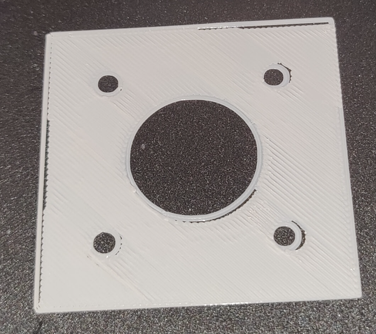
I have been 3d printing for a very long time and I have owned a lot of different machines but I have never built my own from scratch and I have never had a CoreXY printer. I tried my first test print today and below is a photo of my first layer and I have never seen anything like this.
I don't believe I am skipping steps as I'm not hearing anything from the steppers. I even tried making the belts very loose to alleviate some stress on the steppers and the result was the same, and I have the print speed very low. Lastly I have done a backlash test with a dial indicator in both X and Y at max speed and max accel and I always return to within .001 or .002" of where I started.
The gantry and bed are very rigid so I don't think they are to culprit. I don't currently have any features turned on like input shaping or pressure advance. I'm wondering if it could be something weird with the way the steppers interpolate their position?
Any advise would be much appreciated. Thanks.

-
Your first layer actually looks pretty darn good .... having said that, could there have been a missed steps in the print? Maybe your currents set for x and y are two low?
Did you started the infill on the lower left of the picture and it filled to the upper right? Notice that the lower left looks perfect. Then it looks like your nozzle gap increased a bit (have you done a bed mesh? how many points? Was it activated?) just short of the first hole, then the gap of the line to the hole shows up and it gets worse. No idea why the gap opens up on the upper right.
Anyway, check if your motor currents are right or if there is another possibility of skipping (maybe a tight spot in the carriage?)Edit: the upper gap might be consistent with the lower gaps ..... don't know
-
@jens55 Yes I suppose I should clarify. There is a gap on the left perimeter that should not be there. At the top and bottom the gap is small and in the middle it is bigger. On the right the infill actually overlaps the perimeter. On the right side at the top it overlaps so much that it goes past the perimeter. So it's like the entire infill is shifted off to the right. I have the steppers set to 800mA. They are from an old CR10S, they are JD42HS40-1004A-02F. Best I could find max current is most likely 1A so I tried to play it safe.
I am running mesh bed levelling with a BL Touch. The bed is 400 x 400 and it's not very flat so right now i'm running 100 probe points until I can do some more testing to find out what is necessary.
-
@graybilldustin, did you have a chance to verify x and y movement is smooth? I would turn the power off and just manually slide the head/carriage back and forth to make sure there are no tight spots.
800 mA is definitely wrong! I just finished conversion of a CR-10 (but not 'S') and my x/y motors are set to 1500 mA. My Jubilee, which is a core x/y, has motor currents set at 2800 mA !!! It uses 2.5 A motors but that rating is RMS and not peak so my motor currents are set to 0.8 * sqt2 * 2.5A.
Another way of verifying that you don't have enough power is to just load the gantry a bit with your hand to see if there is plenty of spare power or not.
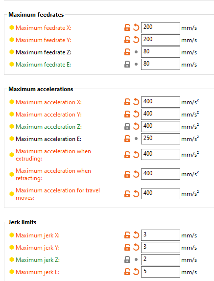
I can't comment on the ratings of the motors ..... they might not be powerful enough.Edit: I agree with your 1000ma for the current rating of your motors. I would crank the current right up to 1000mA. You might be right at the edge of having enough power and cranking things up might just give you enough power. You can also reduce the maximum speed and acceleration in order to get to a workable setup.
I hope you are set up for 24V instead of 12V -
800 mA is definitely wrong!
Sorry to contradict, but my CR-10 steppers run happily at 800 mA from the very beginning, without ever loosing a single step.
However, I agree with you in that @graybilldustin should check the mechanics, and maybe the steppers are a bit weak for a CoreXY, so I underscore your recommendation:You can also reduce the maximum speed and acceleration in order to get to a workable setup.
@graybilldustin Looking at your sample print, the printer seems to lose steps when re-positioning the printhead, not during extrusion. Try to reduce the max. moving speed in your slicer.
-
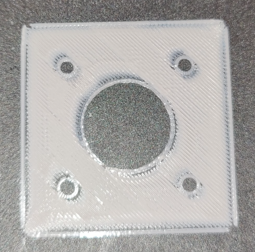
I turned everything way way down and I get slightly different but similar results:


-
@graybilldustin, I suspect you are running into issues of parameters being too low but I have never seen this particular problem. Try bring maximum feed rate of x and y to 50 mm/sec for testing purposes before worrying about speed. Basically your printhead should move painfully slow at this point.
Did you check the mechanics? Did you increase motor current?
One other thing I just thought of - check that all your idlers are running smoothly. You will need to take your belts off for that. When your belts are off this will also allow for better assessment of smooth carriage and gantry movement.
I assume you have not monkeyed with pressure advance yet as this might cause a much reduced extrusion rate at the point where the printer switches direction -
@infiniteloop, are you talking about the current while the motors are in a CR10? The core x/y system requires more power than the cartesian system of the CR10.
-
Try and bring your E jerk up to maybe 50.
-
@jens55 I forgot to answer that in the last post. Without belts the carriage is so smooth that it moves to one corner under gravity because my workbench is not perfectly level. With the belts on and the set screws of the stepper pulley loose it is still +very smooth and easy to move so I don't think it's that.
The last picture I posted doesn't really seem to have an offset like the first photo did it looked more to me like under extrusion at the end of a move but as I said I have pressure advance turned off. Well I decided to take a look at the PA settings while printing and found out that Prusa Slicer was modifying my PA settings during the print. I didn't even know this was a setting in there but it was set to 0.4 which is way too high for the Hemera hotend I have. I set the PA in Prusa Slicer to 0 until I have time to properly calibrate and now the first layer is looking more like what I would expect so I think I had a combination of skipping steps and bad PA settings. Still a lot of calibration to do but at least i'm now where I expect to be. Thanks for all the input.
-
@graybilldustin glad I could help! Good luck !
-
The core x/y system requires more power than the cartesian system of the CR10
Exactly. But instead of running the CR-10 steppers hot, it might be better to replace the two XY steppers with more capable ones (like those your Jubilee is equipped with?).
-
@infiniteloop yes, that would be the preferred solution and one that would give WAY better speeds and acceleration. I would however suggest that the motors can actually take more than 1000 ma (you are setting peak current in the configuration but the motor rating is RMS) so 1000 mA should be just fine for the motors until replacements can be sourced/afforded.
-
@jens55 said in Print Artifacts:
............ The core x/y system requires more power than the cartesian system of the CR10.
How on earth do you come to that conclusion? For any XY move other than at 45 degrees on a CoreXY, both motors contribute to motion thus requiring less power per motor. For 45 degree moves it's only one motor but the belt path of the motor is sqrt2 x the length of the diagonal being printed so there is a gearing effect meaning the available motor torque is effectively increased by a factor of approx 1.4. Again, that's still less power per motor not more. The worse case moving mass on a Corexy is the print head plus the X rail, whereas on a Cartesian it is the print head, plus the bed and it's associated heater, heat spreader and build surface, plus the weight of the part being printed, so likely higher on a Cartesian than a CoreXY.
-
@deckingman said in Print Artifacts:
on a CoreXY, both motors contribute to motion thus requiring less power per motor.
True, but in case of fast direction changes (rapid accel of a single stepper), you need a considerable amount of holding torque on the other one. That's at least what I see missing in the OP's first photo.
-
@deckingman, my reason is because of the WAY longer belt path on a core xy together with more idlers. While I have never run tests, it just seems to make sense.
-
@jens55 The extra weight of longer belts on a core XY is insignificant as is the weight of the moving idlers when compared to the moving mass of a "bed slinger". Couple that with the fact that both motors contibute to motion for anything other than 45 degree moves and the 1.4 gearing effect on those moves means that a CoreXY will always have more torque available than a Cartesian. The only exception might be 45 degree, single motor, high speed moves where, because of the gearing effect, the motor turns faster and could potentially reach the point where the torque curve starts to drop. But it would need to drop to the point where the torque is 1/sqrt2 of peak torque where it might become an issue. On my machine, with my motors, that's about 550mm/sec.
By way of an additional data point, I used to have 6 extruders mounted on a second (UV) gantry above the XY gantry. The moving mass of this set up was circa 3Kgs which I could accelerate at 2000m/sec^2 up to 350mm/ sec using a pair of Nena 17s with quoted torque of 59Ncm..