SSR controlled heater setup query
-
@900turbo what type of SSR is it? can you post a photo?
-
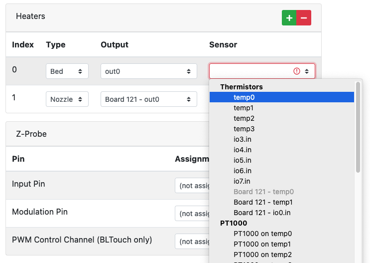
@900turbo It looks like the configuration tool doesn't know about using 'pson' for an SSR. You will need to edit your config.g once it has been created. Select one of the unused options for now, then edit the M950 line in config.g to use
psonrather than, for example,out0. It should look something like this:; Heaters M308 S0 P"temp0" Y"thermistor" T100000 B4138 ; configure sensor 0 as thermistor on pin temp0 M950 H0 C"pson" T0 ; create bed heater output on out0 and map it to sensor 0Wire the SSR between the +5V pin and pson pin, as described for the EXT_5V_IN connector here https://docs.duet3d.com/Duet3D_hardware/Duet_3_family/Duet_3_Mainboard_6XD_Hardware_Overview#description-of-connections.
For your temperature sensor, measuring the resistance at room temperature with a multimeter should give a sense for what the sensor is. If you can heat the bed up a bit, with a hair dryer, then measure the resistance again. If the resistance falls as it gets hotter, it is a thermistor, if it rises, it is a PT1000 or PT100. Though it could be a thermocouple! Report the resistances you measure. Most likely it's a 100k thermistor. If you can post a photo of the sensor, that may also help.
With a 6XD and 1LC selected, I can select temp0 as the pin for the temperature sensor. I'm not sure why you can't.

Ian
-

Here is the SSR
-
@900turbo you can just use a heater (as long as the input voltage is less that 32v) or fan output (set to 12v if the input voltage is greater than 32v) to control that then, no need to use the EXT_5V_IN.
Make sure you add a mains ground to the mounting screws of the SSR too -
@droftarts Okay , I’ll attach a photo of the sensor and will try the multimeter testing and report the results of it back to you. Am I wrong wiring the SSR Control to the EXT_5V_IN connector then ?
Thank you.
-
@jay_s_uk Its a mains heater , so I was in belief of using EXT_5V_IN via the SSR to control it as this was how it was setup on the original board.
What do you mean by "you can just use a heater (as long as the input voltage is less that 32v) or fan output (set to 12v if the input voltage is greater than 32v) to control that then"Thank You.
-
@900turbo the thermistor is probably a 100K NTC 3950
and use a heater or fan output to control the SSR as thats the usual way.
see here https://docs.duet3d.com/en/User_manual/Connecting_hardware/Heaters_bed#bed-heater-driven-using-a-solid-state-relay

-
@900turbo said in SSR controlled heater setup query:
I can't really tell from the picture what the sensor is, though heater pads do often use a thermistor. Take the resistance readings and report back.Am I wrong wiring the SSR Control to the EXT_5V_IN connector then ?
No, it is supported. Though if you want to turn off the PSU, it's best to use pson for that. As @jay_s_uk says, you can use a heater or fan output, or even an IO pin, so long as the signal voltage is within the limits of the input on the SSR (3 to 32V on yours).
Ian
-
@droftarts Okay I’ll show you the current SSR To MB setup
-
This post is deleted! -
-
@900turbo That looks fine. Like I said, you can use pretty much any I/O out pin (though it is slightly more complicated on the 6XD because of the opto isolated outputs), and the PSON pin is basically just another switchable pin.
Ian
-
@droftarts Just thought I would check.
Thanks for the help Ian. -
@droftarts
I took the readings at 200ohmsRoom temperature 30.2
25 degrees = 30.1
50 degrees = 30.0
70 degrees = 30.1
so only a very slight drop in resistance followed by a rise not sure what this means ?
-
@900turbo said in SSR controlled heater setup query:
I took the readings at 200ohms
I don't know what you mean by that? Do you mean you get 200 x 30 = 6000 ohms? I'm used to modern digital multimeters!
Check you are measuring the resistance of the temperature sensor, by measuring ohms across the two wires that come from the bed. Looking at your picture of the bed, these are the red wires. The second pair of wires, the thicker white ones, are for the heater. Usually, these will be low resistance. Check you're measuring the correct wires, they will be the thinner ones.
For a 100k thermistor, you should get something like:
25 degrees = ~100k ohms
50 degrees = ~33K ohms
70 degrees = ~15k ohmsIan
-
@droftarts
 I mean this as in 200 set on the multi meter , there are 5 pins on the heater bed loom of which only 2 produce a reading so I assumed it’s temp sensors wires
Thank you
-
@900turbo can you show a picture of the 5 pins? Try setting the meter to 20k or 200k.
Ian
-
@droftarts at 20 and 200k I don’t get a reading just 0.00
-
-
@900turbo 30 Ohms sounds more like the heater resistance than a temperature sensor. Is it 110V mains or 240V? If it's 240V then using ohms law, 30 Ohms would mean it draws 8 Amps which is about 2,000 watts. If its 110V then 30 Ohms would mean about 3.7 Amps giving about 400 Watts. Do either of those wattage figures sound like the spec for your heater? If so, that confirms that you are measuring the heater resistance, not the temperature sensor. If that's the case, try again with your meter set to read 200K.

