CreatBot F430 Another Transformation
-
This post got me started down the rabbit hole. I've now seen how far down it goes as I'm just reaching the bottom. So I figured I'd share my project.
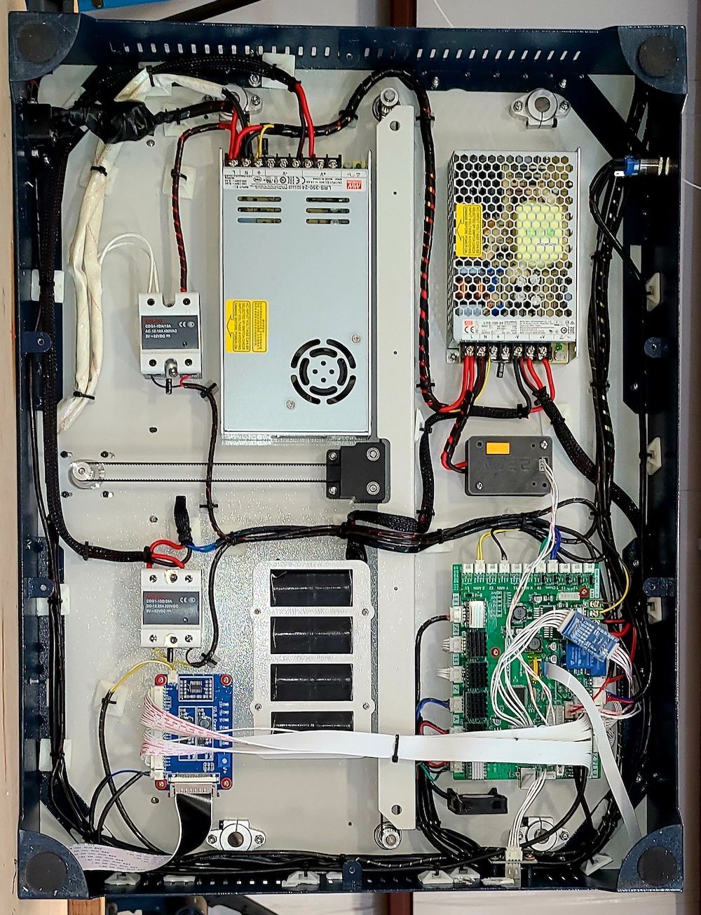
Here is the stock electronic area as I received the F430...
...and here is the modified Duet3D electronics.
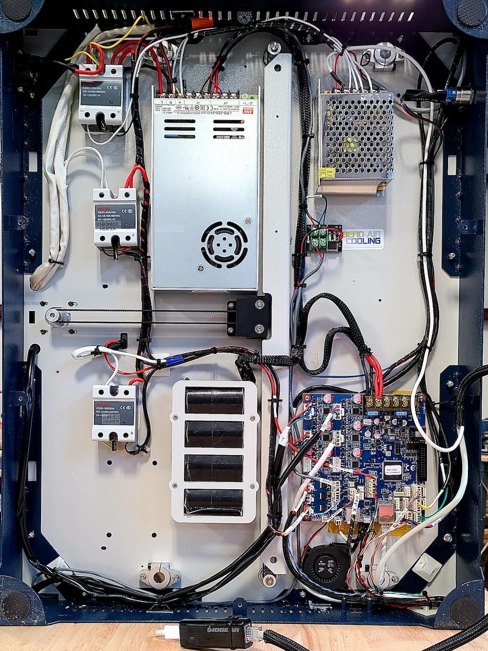
Quite interesting that the original design had two 24v power supplies. I replaced the smaller one with a 5v power supply that powers the Wifi to CAT5 adapter behind the PanelDue, the Dotstar LED's and the SSR which turns on the main 24v power supply. It could also power a future SBC.
The lower SSR controlled the build-plate-heater from the 24v PS. I made the mistake of using the same SSR to power my 110V modified build plate heater. That is a DC-SSR which looks identical (almost) to the AC-SSR. So as soon as I turned on the power the build plate was heating with 55VAC since there is a blocking diode in the DC-SSRs. Lesson 1.
I found this nice PanelDue enclosure on one of the STL depositories. This worked perfect as the F430 has a recessed area with status lights and the old USB socket that needed to be covered.
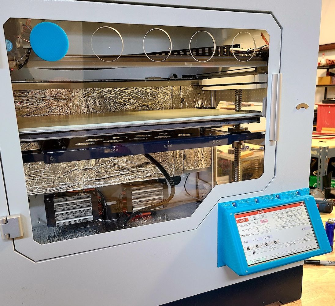
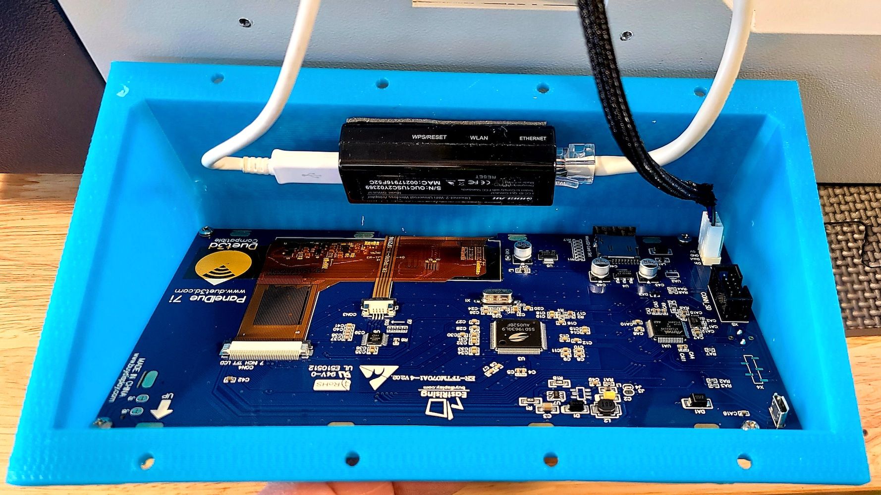
This also provided a perfect place to hide the IOGEAR WiFi to Cat5 adapter. This device works great and is simple. Though I didn't think it would perform well enclosed in a metal box. So this location was a welcome find, and it works.
The Berd Air Pump fit nicely in one of the unused spool bays in the back of the printer. This bay is unused because I keep a filament dryer beside the printer and feed from that. Though I am currently using one bay for PLA to print these blue parts.

Since the enclosure is heated, so I decided to draw air from outside the box. The mount holds the pump with cut tubing pieces in attempt to reduce vibration. At 40% the pump, pumps plenty of air and is hardly audible. Get's noticeable above 45%I'll post print head and build plate pics some other day.
Thanks everyone who helped with my questions on this forum.
-
Configuration:
This has been where I continue to play. Not having any prior knowledge of G/M code there was a steep learning curve. But today I finally felt that everything was working well enough to share. So here is my Config.g and Homeall.g Homeall is included since that I where I setup the StealthChop stuff.A note about the StealthChop, I found (until something gets changed) that Y axis runs better with it off. But X absolutely needs it.
; Configuration file for Duet 3 (firmware version 3.3)
; executed by the firmware on start-up
;
; generated by RepRapFirmware Configuration Tool v3.3.10 on Fri Jun 10 2022 15:08:30 GMT-0700 (Pacific Daylight Time)

; General preferences
M575 P1 S1 B57600                                  ; enable support for PanelDue
G90                                                ; send absolute coordinates...
M83                                                ; ...but relative extruder moves
M550 P"F430"                                       ; set printer name

; Network
M551 P"F430"                                       ; set password
M552 P192.168.0.200 S1                             ; enable network and set IP address
M553 P255.255.255.0                                ; set netmask
M554 P192.168.0.1                                  ; set gateway
M586 P0 S1                                         ; enable HTTP
M586 P1 S0                                         ; disable FTP
M586 P2 S0                                         ; disable Telnet

; Drives
M569 P0.1 S0                                       ; physical drive (X axis) 0.1 goes backwards
M569 P0.2 S0                                       ; physical drive (Y axis) 0.2 goes backwards
M569 P0.3 S1                                       ; physical drive 0.3 goes forwards
M569 P0.4 S1                                       ; physical drive 0.4 goes forwards
M584 X0.1 Y0.2 Z0.3 E0.4                           ; set drive mapping
M350 X16 Y16 Z16 E16 I1                            ; configure microstepping with interpolation
M92 X78.82 Y131.23 Z640.00 E415.00                 ; set steps per mm
M566 X900.00 Y900.00 Z60.00 E120.00                ; set maximum instantaneous (JERK) speed changes (mm/min)
M203 X6000.00 Y6000.00 Z600.00 E1200.00            ; set maximum speeds (mm/min)
M201 X500.00 Y500.00 Z20.00 E250.00                ; set accelerations (mm/s^2)
M906 X800 Y1100 Z1200 E650 I30                     ; set motor currents (mA) and motor idle factor in per cent
M84 S30                                            ; Set idle timeout

; Axis Limits
M208 X0 Y0 Z0 S1                                   ; set axis minima
M208 X420 Y300 Z290 S0                             ; set axis maxima

; Endstops
M574 X1 S1 P"io1.in"                               ; configure microswitch endstop for low end on X via pin io1.in
M574 Y1 S1 P"io2.in"                               ; configure microswitch endstop for low end on Y via pin io2.in
M574 Z2 S1 P"io5.in"                               ; configure microswitch endstop for High end on Z via pin io5.in
;M574 Z2 S2                                         ; configure Z-probe endstop for high end on Z

; Z-Probe
M950 S0 C"io7.out"                                 ; create servo pin 0 for BLTouch
M558 P9 C"io7.in" H5 F2000:100 T6000               ; set Z probe type to bltouch and the dive height + speeds
G31 P500 X-4 Y75.5 Z3.1                            ; set Z probe trigger value, offset and trigger height
M557 X5:400 Y76:286 S30                            ; define mesh grid

; Heaters
M308 S0 P"temp0" Y"thermistor" T100000 B4138       ; configure sensor 0 as thermistor on pin temp0
M950 H0 C"out3" T0                                 ; create bed heater output on out3 and map it to sensor 0
M307 H0 B0 S1.00                                   ; disable bang-bang mode for the bed heater and set PWM limit
M140 H0                                            ; map heated bed to heater 0
M143 H0 S160                                       ; set temperature limit for heater 0 to 160C
M308 S1 P"temp1" Y"pt1000"                         ; configure sensor 1 as PT1000 on pin temp1
M950 H1 C"out1" T1                                 ; create nozzle heater output on out1 and map it to sensor 1
M307 H1 B0 S1.00                                   ; disable bang-bang mode for heater  and set PWM limit
M143 H1 S420                                       ; set temperature limit for heater 1 to 420C
M308 S2 P"temp2" Y"thermistor" T100000 B4138       ; configure sensor 2 as thermistor on pin temp2
M950 H2 C"out2" T2                                 ; create chamber heater output on out2 and map it to sensor 2
M307 H2 B1 S1.00                                   ; enable bang-bang mode for the chamber heater and set PWM limit
M141 H2                                            ; map chamber to heater 2
M143 H2 S70                                        ; set temperature limit for heater 2 to 70C

; Fans
M950 F0 C"out4" Q3000                              ; create fan 0 on pin out4 and set its frequency
M106 P0 C"Print Cooler" S0 H-1                      ; set fan 0 name and value. Thermostatic control is turned off
M950 F1 C"out5" Q4000                              ; create fan 1 on pin out5 and set its frequency
M106 P1 C"HotEnd" S0 H1 S0.5 T100                  ; set fan 1 name and value. Thermostatic control is turned on
M950 F2 C"out8" Q500                               ; create fan 2 on pin out8 and set its frequency
M106 P2 C"onXstepper" S0.15 H-1                    ; set fan 2 name and value. Thermostatic control is turned off
M950 F3 C"out9" Q500                               ; create fan 3 on pin out9 and set its frequency
M106 P3 C"Duet-board" S0.1 H-1                     ; set fan 3 name and value. Thermostatic control is turned off

; Tools
M563 P0 D0 H1 F0                                   ; define tool 0
G10 P0 X0 Y0 Z0                                    ; set tool 0 axis offsets
G10 P0 R150 S0                                       ; set initial tool 0 active and standby temperatures to 0C

; Custom settings are not defined

; Miscellaneous
M501                                               ; load saved parameters from non-volatile memory
M911 S10 R11 P"M913 X0 Y0 G91 M83 G1 Z3 E-5 F1000" ; set voltage thresholds and actions to run on power loss
M150 x0 R100 U100 B100 P100 S107				   ; set DotStar LEDs (dim white)
T0                                                 ; select first tool
; homeall.g ; called to home all axes ; ; HOME X AND Y G91 ; relative positioning G1 H2 Z5 F6000 ; lift Z relative to current position G1 H1 X-425 Y-305 F3000 ; move quickly to X and Y axis endstops and stop there (first pass) G1 H2 X5 Y5 F6000 ; go back a few mm G1 H1 X-425 Y-305 F360 ; move slowly to X and Y axis endstops once more (second pass) G90 ; absolute positioning ;stealthchop tuning AT1 M18 X Y ; disable x and y steppers M569 P0.1 D3 V5 H5 ; enable stealthchop and set tpwmthrs and thigh for X ;M569 P0.2 D3 V5 H5 ; enable stealthchop and set tpwmthrs and thigh for Y M915 P0.1 T5 ; set tcoolthrs for X [needed if stallguard is not used???] ;M915 P0.2 T5 ; set tcoolthrs for Y [needed if stallguard is not used???] M17 X Y ; enable x and y steppers [will this enable full run current or idle current???] G4 P150 ; pause for 150ms to satisfy AT1 condition G92 X0 Y0 ; set home positions again after position loss due to M18 G90 ; absolute positioning ;stealthchop tuning AT2 (and goto probe bed-center) G1 X209 Y67.5 F3000 ; tuning move at "typical speed" that is nearly a straight line... ; ...in order to move both steppers (CoreXY) significantly i.e. >400 full steps @ 60-300RPM ; HOME Z G30 ; home Z by probing the bed G91 ; relative positioning G1 Z25 F1000 ; lift Z relative to current position G90 ; absolute positioning -
Build Plate was completely rebuilt. Stock build plate was a piece of boron glass (I believe) with four studs glued on. It used a 24VDC heater pad that would barely get to 45˚C. Scraped that (well, just put it in a dark corner for now).
The new build plate is a 1000W 120V Keenovo sandwich topped with a layer of 1/4" tempered plate...

The 5mm silicon foam does wonders for the heating ability. It's hard to believe this is not standard on new printers.
The 1/4" glass is overkill and quite heavy. Upon the finish of my first print on it the build plate costed all the way to the bottom - very strange. I found that I had been using M84 in the post process script of the slicer. Changing it to "M84 X Y" should solve the Z motor idle hold from turning off.Stock print heads is what got me thinking that an update might be possible. Problem was that I was getting heat creep as the little fans were poorly implements and starved for air. I couldn't heat the chamber and keep the filament from jamming on certain filaments. Here is a picture of the stock heads.
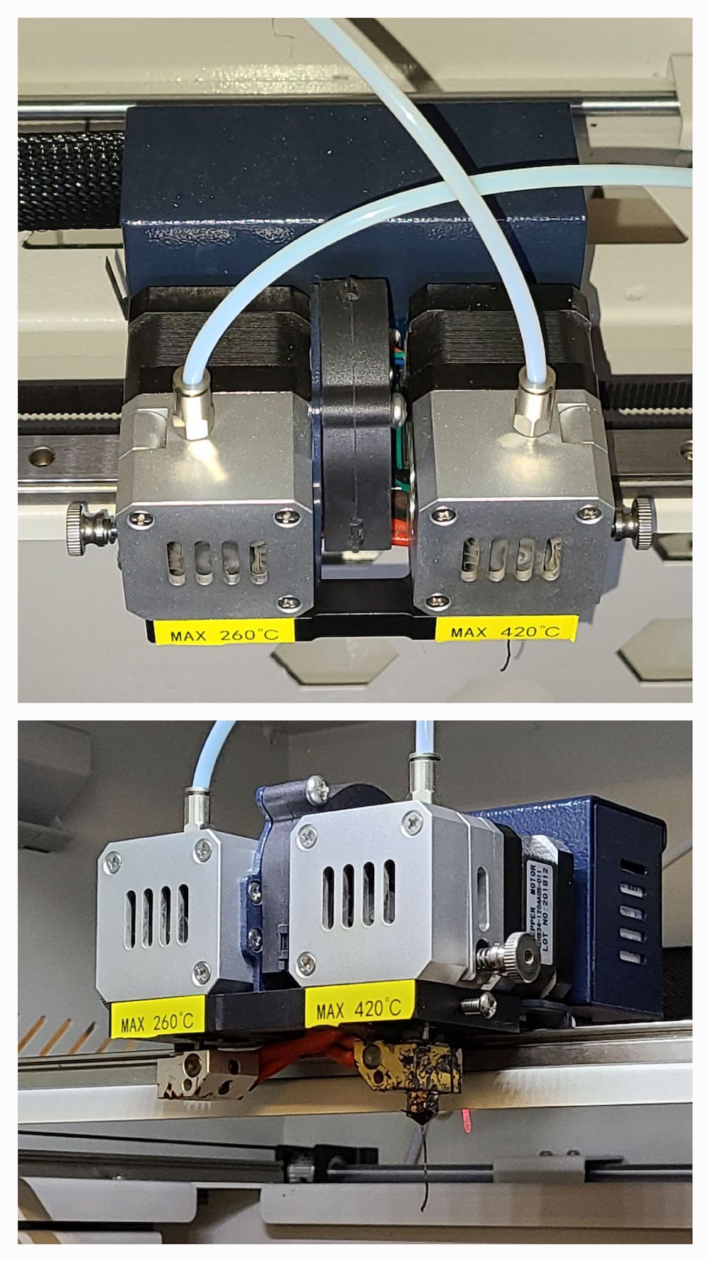
Very nicely built but not as functional as I would have liked.Since I ever only used one head, that is what I switched to...
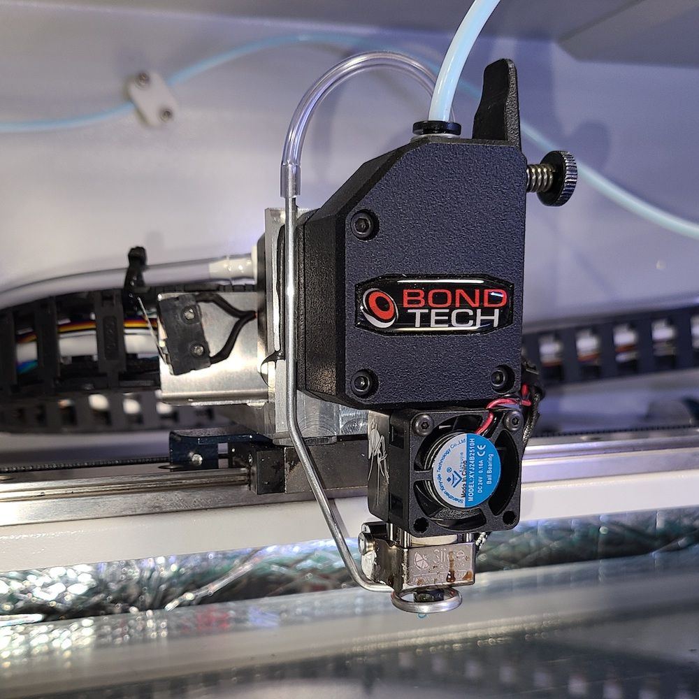
So far I like the mosquito and BMG extruder. If I have trouble with heat-creep again the next step would be to convert to water cooled which should be fairly easy since mosquito make a water cooled version of what I have here. So it would just require one part plus the water.Well that's about all I have to say about that subject.
Have a blessed Independence Day celebration
----(for my friends in the USA) -
Looking great! Keep the pictures coming if you've got 'em. Boy, your electronics section is so much neater than mine, making me think I may need to go knock mine over and see what I can do.
Original config is interesting; mine did not have the second 24v power supply when purchased in mid 2019. Otherwise, looks very similar, and I see they're still just duct-taping the capacitors together.
One of your images reminds me of that little L-beam under the x-axis rail. I have switched to stainless-endcap, high-temperature rails, so it's not 100% comparable to your setup, but still, pretty sure you can remove that. Looking at it, I couldn't imagine it actually added any useful rigidity, and indeed it doesn't seem to. Removing it drops about 120grams from your y-axis load, and also gains you additional clearance if you ever do sequential/multi-part printing. The rail itself is more than enough to carry the gantry, in my experience.
Getting an air pump in the spare bay as you have is currently high on my to-do list, currently modeling a TPU mount for it. I've just finished a new watercooled Dyze extruder with cooled toolboard, but it will be a Berd setup, so I can't make the swap until I get the pump setup.
-
@maestro said in CreatBot F430 Another Transformation:
I have switched to stainless-endcap, high-temperature rails
Can you give more info on your rails?
The thought of removing the 'L' beam never occurred to me since I didn't do any mechanical changes besides the print head. I'll take a look at that - thanks.
If you want any specific pictures let me know.
-
@brs
The rails are THK RSX series, good to 150C. High-temp rails were by far my biggest sourcing issue in putting together a truly high-temp enclosure; no one wants to sell in small quantities, but I did eventually find that THK.com will deal direct, so I bought straight from them. Lead time was about two months, and they aren't cheap. However, with all my steppers either out of the enclosure or water-cooled, I'm no longer limited by the rails.Y-axis (x2): RSX15M1NUU+390L
X-axis: RSX15M1NUU+670LThe hole-spacing is standard; the y-axis rails will bolt right in place, no modification needed. The X-axis will be too long, you'd have to cut the rail down. I don't remember if the rails will fit into the original Y-gantry blocks. I know they're not the exact same size as the original rails, but I don't remember if they are bigger or smaller. I had made my own gantry blocks anyway. On that note, I will mention that the belt anchoring on the blocks is a source of ringing that you may find yourself dealing with sooner or later anyway (at least on mine it was just allen screws pinching straight onto the belts, no blocking).
-
Hey guys, I found this thread in a Google search, and made an account so I could reach out. I recently bought a creatbot F430 and I’m trying to see what I need to make it Wi-Fi compatible, compatible with other slicers, and more modern and easy to use. This is my fifth 3-D printer, second 3-D printer, and I’m very familiar with G code and CNC machine, metal, turning, etc. i’m just trying to figure out the electronics part I’m already insulating and adding heat sources, I was hoping for some input on firmware and hardware for the electronics upgrades? If anyone has some tips, I would greatly appreciate the advice.
-
@Cj110109 it looks like the OP dis a great job using the Duet 3 6HC however in checking out the config the max current they are using for the motors in 1.2A and they are using 4 (single extruder) so it looks like a mini5+ would be able to do the job:
https://docs.duet3d.com/Duet3D_hardware/Duet_3_family/Duet_3_Mini_5+_Hardware_OverviewYou also have expandability within that to keep the second extruder if you wanted to. I cant comment on the hardware elements of the upgrade and how much work that was.