Precision Piezo Delta bed mount
-
Hello everybody.
I'd like to use precision piezo z-probe (underbed) on my delta printer.
What is the best way to mount the bed on the frame with the piezos?
I think it should allow some little movement in z direction, but should be stable in x/y direction.I will be happy if somebody can share some ideas for bed mount...
-
@cosmowave Maybe this design is a good starting point?
-
@cosmowave Speaking from my own experience I can advise against putting your z-probe(s) under the bed. There will always be a minute amount of defflection in the bed itself as the nozzle contacts it to trigger the probing system. This deflection will cause offsets to your trigger height that depend of the bed location (0 right about a sensor and more as you probe furter away).
A system like this not unuseable, I operated my machine like this for multiple years. At the same time, it is far from perfect, especially if you have a large-ish bed and want to print larger things.
-
-
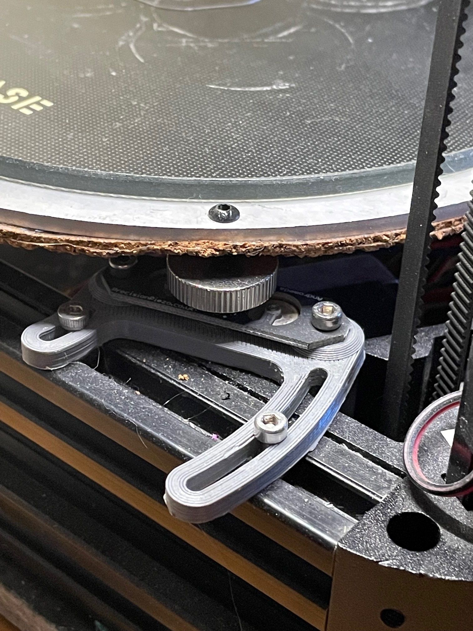
This is one of the three mounts I built to hold my piezo sensors under my delta's print-bed. The bed just has a large knurled nut on the m3 bolt to make each mount point adjustable in Z. The bolts are long enough I can adjust the bed up and down through 5mm which is plenty for tramming.
It's only held down on the piezo mounts by its own weight.
-
@steveyyc Thanks for the picture.
Do you never had a shift in x/y direction? How big is your bed? -
@cosmowave I have a stock 220mm build plate with a 200mm ultrabase plate on it. The bed is a little loose at room temperature with a fraction of a mm play in X/Y but when it's hotter than 50 degrees it does not move in x/y. If I want it to be rigid at room temperature I can loosen the M3 nearest the towers and rotate the mounts inward a bit and take the slack out of the system (That's why I have the adjustment slots in the mounts).
I have considered adding some springs under the bed to pull the three mounts inward at any temperature which would get rid of the tiny bit of slop when the bed is cold but I rarely print on a cold bed so I haven't gotten around to it.
-
@cosmowave said in Precision Piezo Delta bed mount:
@nxt-1 Do you know how much the deflection will be approx., when i use the discs in "fully squish mode" (not bending, pressure on the full area of the disc)
I am not sure what you are asking here. Also the amount of deflection is not really the point, just that it is different everywhere and just about impossible to know without testing.
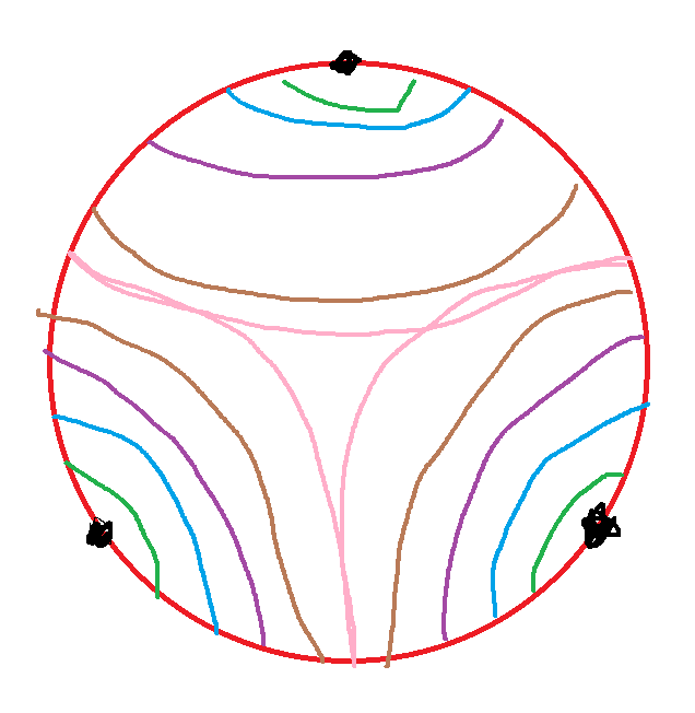
I have made a very crude paint drawing to better illustrate what I mean. Usually with under-bed-probing, three probes (black) are used, spaced similarly to the towers. If you were to probe right above a black dot you would get a trigger height of something in the order of -0.1mm. As you probe furter away from a sensor the bed itself would flex more and more before enough force is applied on the sensor to trigger. Obviously if you go far enough from one sensor you get in the range of one of the other sensors so you get these lines of similar flex/trigger height.
How much the flex in the bed is depends grealty on the diameter of the bed and the thickness.Hope this helps
-Nxt
-
@nxt-1
I think this flex/bed-sagging might be compensated is some part by the leverage of the system.The piezo sensors furthest from the probe point are being flexed by the bed as well as the piezoelectric sensor closest to the probe point but the deflection at those point is larger because the probe point is acting as the input of a third class lever with the closest piezo sensor acting as the fulcrum and the further-away sensors are the load.
I suspect the maximum deflection at any point before a signal is detected would need to be a higher frequency harmonic of your sketch with a proportionally smaller deflection amplitude at each anti-node. Since I feel like this is getting into Laplace Transform territory I have to admit my math skills aren't up to quantifying this.
I expect there are a few "worst" places to probe (the midpoint between two sensors for example) which produce low-magnitude signals at two sensors and do not have any moment producing a signal at the remaining sensor.
Anywhere inside the triangle enclosed by the three sensors should produce a signal at all three sensors. Any point outside the line connecting two sensors would produce a signal at the third sensor with negative magnitude (because now its a first-class lever) and that might cause some odd behaviour depending on how the signals are processed in the probe's firmware but so far my installation hasn't had problems interpreting probe results at those locations.
If a very large round bed experiences this sort of measurement inaccuracy then I would suggest the bed is under-supported or under-built anyway and the bed dishing could/should be dealt with by some combination of stiffening and a better multi-point support system similar to that used for telescope mirrors.
-
Well drawn explanation of the piezo sensitivity!
Sorry for necroing this thread, but your drawing inspired me to design a program that can generate a point cloud for probing, that avoids the points near the towers and prefers the points near the underbed piezo's.
Sadly it's made in Grasshopper so I can't share it as a script or executable, but maybe this could be inspiring to someone.
I just finished my DIY Delta printer today and I noticed that the probing wasn't that great across the bed so I wanted to see if I could fix that somehow. Assuming my bed is flat enough, I came up with this, where the colored circles are the piezo locations:
Example with lines drawn:
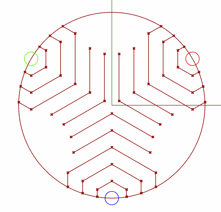
Outermost points culled and I tweaked the amount of points a little bit (and the point data is rounded to whole numbers):
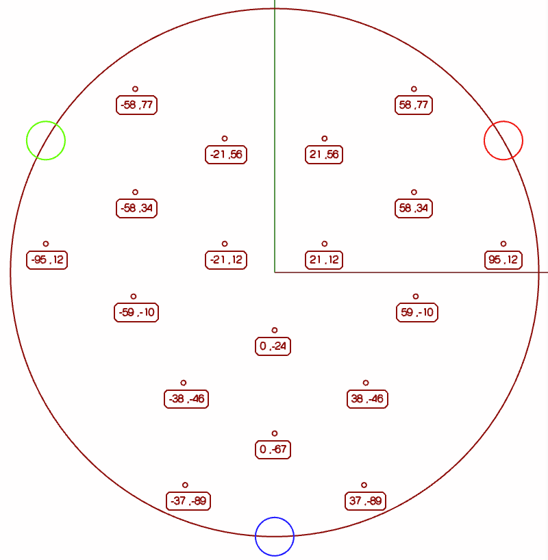
And this is the output point list that can now manually turned into a list for the reiterative probing sequence for example (with the point data rounded to two decimals):
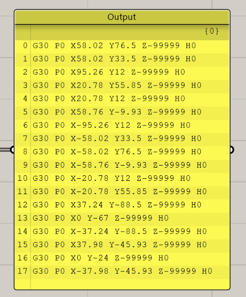
This data can be changed on the fly, so I can see what the probing pattern will look like live without having to first run a script, it's live:
https://youtu.be/0ofXqwViaMcI hope this could serve as an inspiration to someone and if you have ideas of a good type of point distribution I'd love to hear your ideas.
I have yet to try out this set of points but it's kinda late now so I'll do that tomorrow when I'm sharp and present again.
Just a small update on this reply, which I might turn into a post later on if anyone thinks it deserves its own post:
The results are in, initially it had quite a big deviation, but the second probing sequence was an immediate hit:
Calibrated 8 factors using 18 points, (mean, deviation) before (-0.009, 0.034) after (0.000, 0.022) Auto calibration successful, deviation 0.022mmI also incorporated a point sorting algorithm. Before the point list was random, causing long travel times during probing, but now it's just moving from one point to the next closest point making this a painless probing sequence.