Duet 2 Ethernet no connection
-
@camposm7 said in Duet 2 Ethernet no connection:
Windows device manager didn't recognize the board until I reset it a few times.
prey tell; what does it recognize it as? if it shows up as a bossa device then its not flashed properly; if it shows up as a duet then you're good, if it shows up as something else then check the usb device id or install the correct drivers.
-
@beare It does indeed show up as bossa device.
-
Ok well at least it's showing up as something. Since it's showing as a bossa device it means it doesn't have firmware on it.
Please carefully go through the bossa flashing procedure here: https://duet3d.dozuki.com/Wiki/Installing_and_Updating_Firmware#Section_Fallback_procedure_Num_3
-
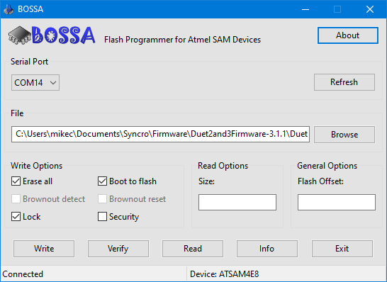
@Phaedrux The directions say Check boxes Erase all, Lock, and Boot from Flash. However there is no boot to flash check box. Am I supposed to check boot to flash?
-
Can you show a screenshot of the bossa window? If you're on windows you should be able to press alt-print screen and then cntrl-v in the post window to paste a screenshot.
-
-
yes I think boot to flash and boot from flash are meant to be the same.
What version of bossa is that?
-
v. 1.9.1
-
Ok, so does it write and verify correctly?
Did you follow the instructions on removing the jumper before flashing?
Remove the erase jumper as soon as the Diag LED lights up. This means you are successfully in programming mode.
Once flashed, power cycle the board and you should now have a port to connect with YAT.
-
maybe try windows key + R, type
cmdand click OK.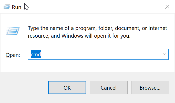
and then paste in the command below in the new window and press enter? (type out the whole path if its not under your own user profile.)
"%ProgramFiles(x86)%\BOSSA\bossac.exe" --port=COM14 -e -w -v -b -R "%USERPROFILE%\Documents\Syncro\Firmware\Duet2and3Firmware-3.1.1\Duet2CombinedFirmware.bin"
Clearly something goes wrong with resetting the cpu after flashing, or its become faulty.
-
Yes, it does Bossa does write and verify correctly.
I followed the instructions to the T, however my diag led is on even after removing the jumper and resetting.
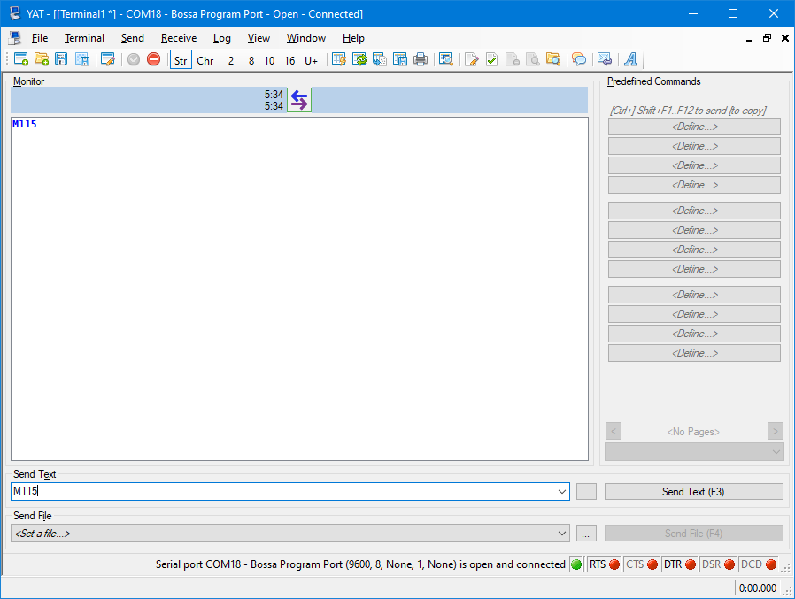
As you can see in the picture it is still listed as a Bossa Program Port. It looks like it's connected to YAT but still unable to respond to Gcode commands.
-
@bearer
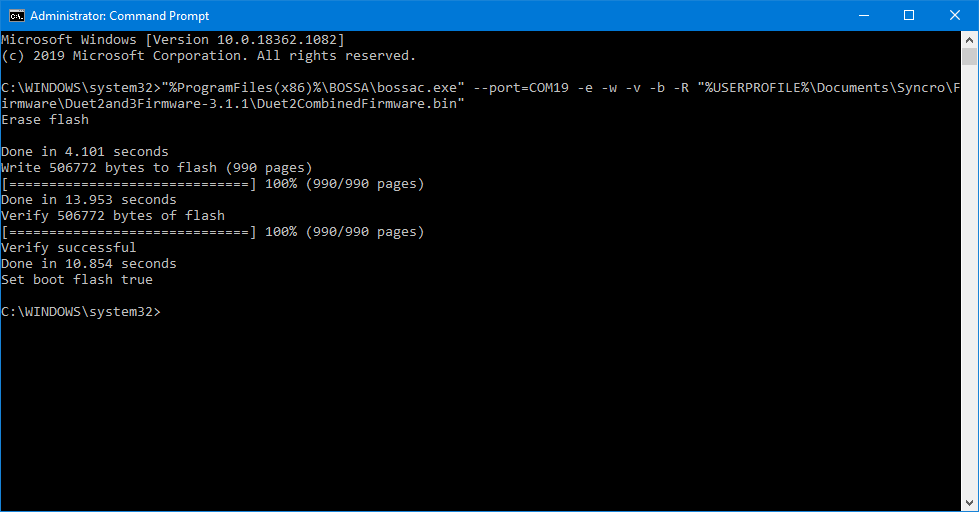
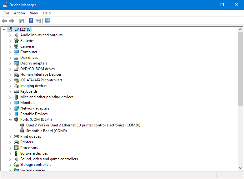
Jackpot! Thank you!
-
so it's working now?
-
@camposm7 said in Duet 2 Ethernet no connection:
I followed the instructions to the T, however my diag led is on even after removing the jumper and resetting.
I think something got lost in translation to be honest, but that is why I suggested using the command line version with the -R flag as it removes the need for manually resetting the board.
Maybe someone could file an issue on the bossa github to have the -R flag function added to the GUI version; would simplify things a little.
-
@Phaedrux I was able to flash the firmware, and while I can now web into the board and shows connection established, my PanelDue contently displays Connecting. None of my macros are displayed on the panel although the web interface does display my macros. My extruder heaters are undefined. No thermistor readings. Some weird things happening. Even a simple M119 reports Endstops - X: no endstop, Y: no endstop, Z: no endstop, Z probe: at min stop
I'm not even sure where to begin with this. It's like it isn't reading the config file properly. Using the same config I was previously using that was working fine before erasing the board and starting fresh
-
that sounds like you flashed rrf3.
this requires some changes in the config. see
https://duet3d.dozuki.com/Wiki/RepRapFirmware_3_overview#Section_Summary_of_what_you_need_to_do_to_convert_your_configuration_and_other_filespost your config.g
-
It may be helpful to create a fresh config set using the online configurator then you can compare it to your current config and see what's all changed.
-
@Veti
What is the best method to post my config for ease of reading? -
post the config.g file into the window here
select it and press the code button -
; Configuration file for Duet WiFi (firmware version 2.03)
; executed by the firmware on start-up
;
; generated by RepRapFirmware Configuration Tool v2.1.8 on Thu Mar 05 2020 07:51:50 GMT-0800 (Pacific Standard Time)

; General preferences
G90                                             ; send absolute coordinates...
M83                                             ; ...but relative extruder moves
M550 P"S110 Tall"                               ; set printer name

; Network
M552 P0.0.0.0 S1                                ; enable network and acquire dynamic address via DHCP
M586 P0 S1                                      ; enable HTTP
M586 P1 S0                                      ; disable FTP
M586 P2 S0                                      ; disable Telnet

; Drives
M569 P0 S1                                      ; physical drive 0 goes forwards
M569 P1 S0                                      ; physical drive 1 goes forwards
M569 P2 S0                                      ; physical drive 2 goes forwards
M569 P3 S0                                      ; physical drive 3 goes forwards
M569 P4 S0                                      ; physical drive 4 goes forwards
M584 X0 Y1 Z2 E3:4                              ; set drive mapping
M350 X16 Y16 Z16 E16:16 I1                      ; configure microstepping with interpolation
M92 X400.00 Y400.00 Z400.00 E420.00:420.00      ; set steps per mm
M566 X700.00 Y700.00 Z212.00 E120.00:120.00     ; set maximum instantaneous speed changes (mm/min)
M203 X4000.00 Y4000.00 Z1000.00 E400.0:400.0  ; set maximum speeds (mm/min)
M201 X200.00 Y200.00 Z80.00 E250.00:250.00     ; set accelerations (mm/s^2)
M906 X800 Y800 Z800 E500:500 I50                ; set motor currents (mA) and motor idle factor in per cent
M84 S50                                         ; Set idle timeout

; Axis Limits
M208 X0 Y0 Z0 S1                                ; set axis minima
M208 X210 Y260 Z500 S0                          ; set axis maxima

; Endstops
M574 X1 Y1 S1                                   ; set active high endstops
M574 Z1 S1                                      ; set endstops controlled by [probe] no, by microswitch 03/07/2020

Z-Probe
M307 H3 A-1 C-1 D-1                             ; disable heater on PWM channel for BLTouch
M558 P9 H1 F120 T5000                           ; set Z probe type to bltouch and the dive height + speeds
G31 P500 X0 Y20 Z2.5                            ; set Z probe trigger value, offset and trigger height
M557 X10:200 Y10:200 S80                        ; define mesh grid

; Heaters
M305 P0 T100000 B4339 R4700                     ; configure PT1000 for heater 0
M143 H0 S100                                    ; set temperature limit for heater 0 to 100C
M305 P1 T500000 B4723 C1.196220e-7 R4700        ; set thermistor + ADC parameters for heater 1
M143 H1 S250                                    ; set temperature limit for heater 1 to 350C
M305 P2 T500000 B4723 C1.196220e-7 R4700        ; set thermistor + ADC parameters for heater 2
M143 H2 S250                                    ; set temperature limit for heater 2 to 350C
M307 H1:2 A250 c160 D5.5 B0 S0.3 		; set max heater power to 60% to reduce overshoot (DNC 03/12/2020)

; Fans
M106 P0 S0 I0 F500 H-1                          ; set fan 0 value, PWM signal inversion and frequency. Thermostatic control is turned off
M106 P1 S1 I0 F500 H1:2 T45                     ; set fan 1 value, PWM signal inversion and frequency. Thermostatic control is turned on
M106 P2 S1 I0 F500 H1:2 T45                     ; set fan 2 value, PWM signal inversion and frequency. Thermostatic control is turned on

; Tools
M563 P0 D0 H1 F0                                ; define tool 0
G10 P0 X0 Y0 Z0                                 ; set tool 0 axis offsets
G10 P0 R0 S0                                    ; set initial tool 0 active and standby temperatures to 0C
M563 P1 D1 H2 F1                                ; define tool 1
G10 P1 X0 Y0 Z0                                 ; set tool 1 axis offsets
G10 P1 R0 S0                                    ; set initial tool 1 active and standby temperatures to 0C

; Custom settings are not defined
