Improving mesh bed compensation with M558 HX
-
Hi everyone!
I think my mesh bed compensation is not working correctly (maybe not working at all). I've tried to vary the H parameter in the M558 command but it didn't get better, always got the same result. It's a cartesian printer with RRF 2.02.
I've tried it with H30 and then G29 S0. I've also sent a M122 command. "Bed compensation in use: mesh".
This is the code in config.g:
M558 P5 X0 Y0 Z1 I0 H5 A3 F120 T6000 S0.01 ; Set Z probe type
G31 P600 X32.7 Y35 Z0.5 ; Set Z probe trigger
M557 X67:270 Y75:265 S101.5:90 ; Define mesh gridhomeall.g:
G91 ; relative positioning
G1 Z5 F6000 S2 ; lift Z relative to current position
G1 S1 X-382 Y-457 F1800 ; move quickly to X and Y axis endstops and stop there (first pass)
G1 X5 Y5 F6000 ; go back a few mm
G1 S1 X-382 Y-457 F360 ; move slowly to X and Y axis endstops once more (second pass)
G90 ; absolute positioning
M564 S0 H0
G1 X33.5 Y27 Z15 F6000 ; go to first bed probe point and home Z
M564 S0 H1
G30 ; home Z by probing the bedhomez.g:
G91 ; relative positioning
G1 Z5 F6000 S2 ; lift Z relative to current position
G90 ; absolute positioning
M564 S0 H0
G1 X33.5 Y27 Z15 F6000 ; go to first probe point
M564 S0 H1
G30 ; home Z by probing the bedI would like to know if there is another way to improve the mesh bed compensation or if I've done something wrong with the H parameter. Look forward to your help, thank you!
-
@sykb said in Improving mesh bed compensation with M558 HX:
M558 P5 X0 Y0 Z1 I0 H5 A3 F120 T6000 S0.01 ; Set Z probe type
Doesn't the H mean , after it as sensed the bed ( eg on the bltouch it's pushed the pin up ) , the height the probe/nozzle will raise .
I've set my H to 2mm , with a H of 30mm it will raise by 30mm after each hit.
-
@sykb said in Improving mesh bed compensation with M558 HX:
M557 X67:270 Y75:265 S101.5:90 ; Define mesh grid
depending on the quality of your bed that might not be enough. Try S10
@sykb said in Improving mesh bed compensation with M558 HX:
RRF 2.02.
Please update to at least 2.0.5.1
also post a picture of the final mesh bed
-
You would know if S was too low , because you would get a error message saying so.
-
@sykb
Are you using a bltouch to home / mesh level / bed compensation ?
-
then try S15
-
-
@sykb
Is your off set correct ?
G31 P600 X32.7 Y35 Z0.5 ; Set Z probe trigger
So this say your probe is 32.7mm to the right of the nozzle X axis and your probe is 35mm to the back of the nozzle Y axis , Correct ?
-
@Veti said in Improving mesh bed compensation with M558 HX:
then try S15
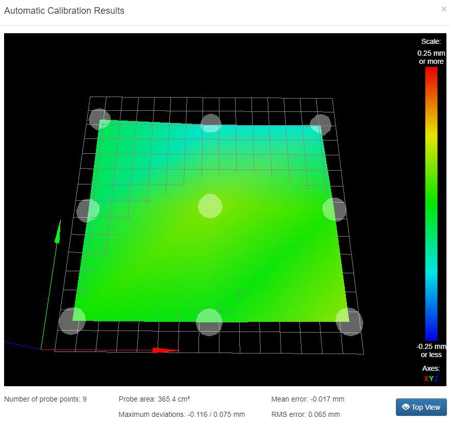
you have not changed this. there are only 9 points in your mesh.
-
@sykb said in Improving mesh bed compensation with M558 HX:
M564 S0 H0
G1 X33.5 Y27 Z15 F6000 ; go to first bed probe point and home Z
M564 S0 H1You shouldn't have to be using M564 at all. I would suggest removing those. If something isn't working without them you've got other problems to solve.
What type of probe is this?
Increasing your grid density will give you a better idea of what the bed surface is actually like. When it's so sparse like you have there could be large variations in between the points that are not captured in the mesh and can't be compensated for.
You can try adding M558 A parameter to increase the repeatability of the probe.
-
@sykb what settings do you use to tell the probing to only probe 9 points? I would like to have that as well. Mine is currently probing about 42 points and I have a glass bed.
-
@deonholt said in Improving mesh bed compensation with M558 HX:
@sykb what settings do you use to tell the probing to only probe 9 points? I would like to have that as well. Mine is currently probing about 42 points and I have a glass bed.
In M557 you use either S or P parameters to tell it the spacing of the points, or the number of points. So if you want 9 points, use P3:3 which will probe a 3x3 grid.
-
@Phaedrux said in Improving mesh bed compensation with M558 HX:
@deonholt said in Improving mesh bed compensation with M558 HX:
@sykb what settings do you use to tell the probing to only probe 9 points? I would like to have that as well. Mine is currently probing about 42 points and I have a glass bed.
In M557 you use either S or P parameters to tell it the spacing of the points, or the number of points. So if you want 9 points, use P3:3 which will probe a 3x3 grid.
Great! Thank you so much.
-
@Phaedrux said in Improving mesh bed compensation with M558 HX:
In M557 you use either S or P parameters to tell it the spacing of the points, or the number of points. So if you want 9 points, use P3:3 which will probe a 3x3 grid.
I tried this but it gave some error:
M557 P3:3 ; define mesh grid 3x3
I think I' missing something to tell it to save it. (I'm learning.)Thanks.
-
@deonholt said in Improving mesh bed compensation with M558 HX:
I tried this but it gave some error:
M557 P3:3 ; define mesh grid 3x3
I think I' missing something to tell it to save it. (I'm learning.)Thanks.
You still have to include the X and Y min/max values.
Frederick
-
-
Not seen sykb on , But I can see lots of faults .
Can't tell what printer he has , but to me the off sets or wrong , the homing files are wrong , and he is not probing the centre of the bed. -
Thank you everyone for your response and sorry for my slow response. I'll try all your suggests.
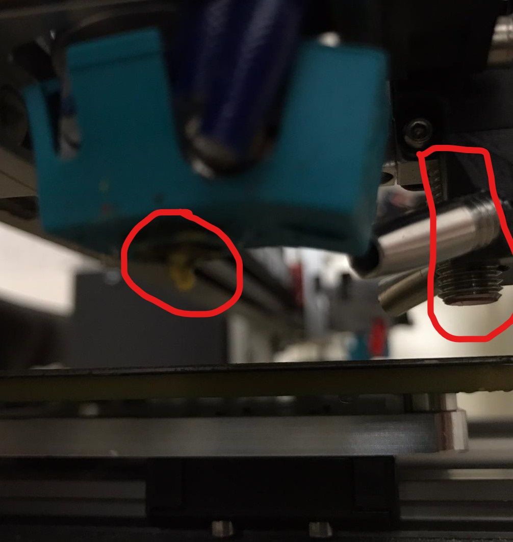
@peter247 yes, the off set is correct. I can show you a picture.

@Veti yes, I have not changed it. I just wanted to show you how it looks with 9 points. I'll update the firmware first to 2.05.1 and try with S10 or S15, as you suggested.
@Phaedrux I've tried adding M558 A parameter in 2.02 and didn't get a better result. I'll try it again but in 2.05.1.
I'm using an inductive sensor as probe. You can also see it on the picture above.
@deonholt yes, you also have to define the X and Y min and max values, as @fcwilt said.
-
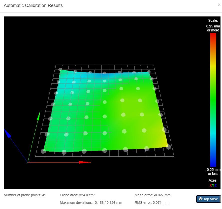
@Veti I've tried S30 (49 points) in RRF 2.05.1 and this is the result:

And then I did a test print but got the same result as before.
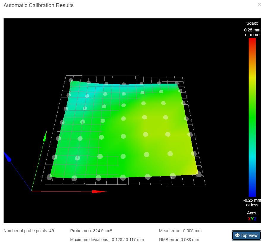
@Phaedrux I've changed the code to S30 in the M557 command and to H10 A6 S0.01 in the M558 command, but there is still no improvement. I've also tried removing the M564 commands in the homing files, as you suggested, but after that I could not home Z at all and got an error report saying: Error: G0/G1: insufficient axes homed.
And this the height map with the changed parameter:

-
@sykb
Your homing could be simpler :-
This is mine !!!; homeall.g ; called to home all axes ; G91 ; relative positioning G1 H2 Z5 F6000 ; lift Z relative to current position G1 H1 X 355 F3000 ; move quickly to X axis endstop and stop there (first pass) G1 H1 Y 355 F3000 ; move quickly to Y axis endstop and stop there (first pass) G90 ; absolute positioning G1 X220 Y175 F4000 ; Move probe to middle of bed 350 x 350 G30I only do a single pass homing on X and Y , don't care if it is a fraction out.
What is your printing area ? , and can the probe go to the edges of the printing area without hitting the sides or hitting the limits ?
