Battling sources of vibration and noise
-
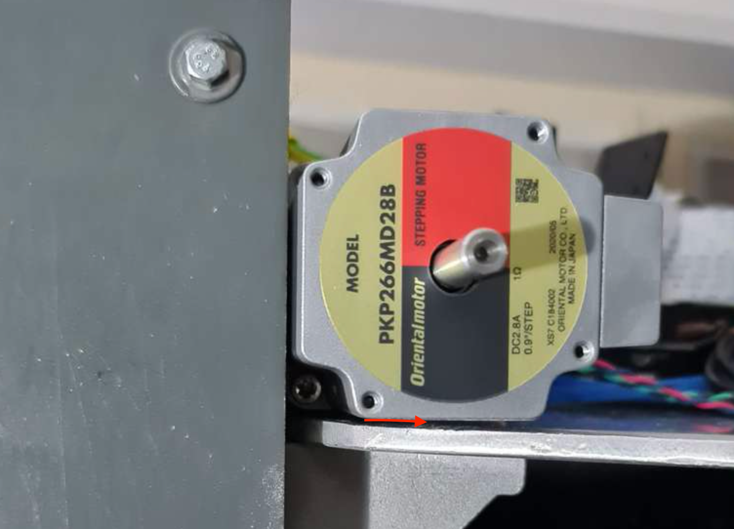
@Nxt-1, just curious - how much deflection is being witnessed between the motor mounting face (the side where isolator is) and the opposite face in the photo? And how, if any, does that differ when the belts are loose/tight?
-
@Kolbi said in Battling sources of vibration and noise:
@Nxt-1, just curious - how much deflection is being witnessed between the motor mounting face (the side where isolator is) and the opposite face in the photo? And how, if any, does that differ when the belts are loose/tight?
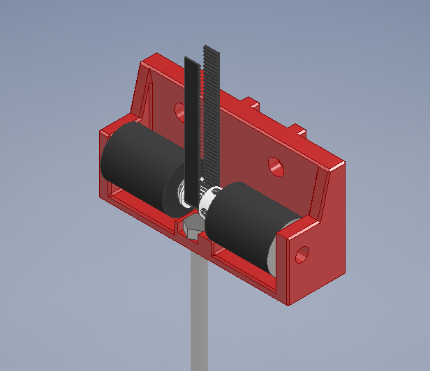
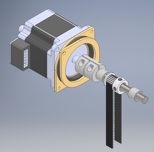
The deflection is practically 0 in any direction with or without belt tension. This is due to the two added needle bearings on either sides of the pulley. See the attached picture of the motor mount without the actual (white) mount piece.
-
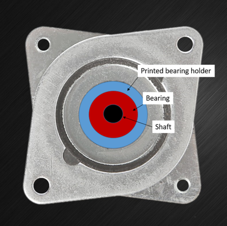
I think your vibrations would them be radiated through the bearing mounts. For an experiment/test; I'd get rid of the bearing closest to the motor, take a spare motor isolation mount, design a bearing holder to fit centerline within it (like how a motor is mounted) and then an 'L' bracket to attach the newly constructed bearing isolation assembly to your plate?
Something effectively like this (the printed bearing holder would obviously need to extend to the mounting points on the flange but I only have powerpoint atm):
-
After some more experimenting I have narrowed down the issue somewhat. Here are some things I have noticed:
- There is no resonance type inter-play between the difference axis through the arms/effector. In fact, the effector is
not involved at all. I removed the effector and arm altogether without any changes observed.
All below items are tested using just one axis and nothing attached to the moving slider. - No belts attached or loosely attached (ie no tension whatsoever) means there are no vibrations.
- With tensioned belts the vibrations kick in but only if the pulley is moving in sync with the motor axle. This can be accomplished by either locking the pulleys with the grub screws or gently pushing the carriage by hand with loose pulleys.
- I tried removing both needle bearings inside the motor mount to see if they are part of the vibration path. They are not, no changes with or without bearings. @Kolbi I believe removing the bearings altogether proves the point you were trying to verify.
- I am not sure if it is due to changes I made along the way, or I just noticed it now but with belts tensioned, a significant part of the noise seems to originate from the bottom pulleys (at the bottom of the printer). To make sure that this is not another case of things rattling against the metal frame, I removed the long 'tension bolt' and tensioned the belt myself by pulling on the bottom bracket real hard
 . The noise remained.
 - I very strongly doubt that the bottom pulley brackets are the actual source though, as they vibrate at the exact same frequency as the motor, suggesting some coupling is involved.
- I don't think it's the belts themselves either, as the frequency should change with varying belt tensions and be touching the belt in various places.
- The two above points lead to be to believe that the belt is acting as a vibration coupler from the motor to the bottom bracket. This is further supported by the fact that the very slight stand still noise/vibration can be heard with matching frequency at the lower bracket as well.
The bottom pulley bracket (supported by needle bearings on either side):
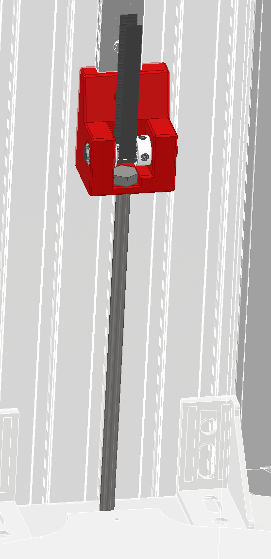
- There is no resonance type inter-play between the difference axis through the arms/effector. In fact, the effector is
-
@Nxt-1 from what you're saying, it seems as if you only get the noise when the motor is torsionally coupled to the belt. It could well be that your pulley tooth passing is a harmonic of the stepper? You have 0.9deg stepper, and are they 20T pulleys? Bearing in mind you've got belt teeth coming into and out of mesh, its possible that could interact excite some of the higher frequencies. That coupled with the long shaft with coupling and you've got quite an interesting system for torsional dynamics and interaction with the motor. Its a common problem with electric car design that the motors are quiet on their own and the reduction gearbox is quiet on its own, but join them together and they both suddenly become very noisy.
I can't remember from the previous posts if you have tried changing the pulleys for slightly different tooth numbers, but it may help. Alternatively, adding some inertia to the motor shaft (motor end and/or pulley end) may help shift the natural frequencies of the two parts of the system so they interact less.
As Kolbi said, if the shaft is being excited it will radiate through the bearings into your mounts. So putting some isolation on the needle bearing supports might help. This might explain why the isolation mounts you fitted didn't have the impact others thought they would? Tbh I'd recommend just mounting that whole motor block on a thick piece of rubber and don't clamp it down too hard.
-
@Nxt-1 said in Battling sources of vibration and noise:
The two above points lead to be to believe that the belt is acting as a vibration coupler from the motor to the bottom bracket. This is further supported by the fact that the very slight stand still noise/vibration can be heard with matching frequency at the lower bracket as well.
Besides what @engikeneer said, the only ideas I have (and these are just spit-balling) at the moment would be to redesign the bottom bracket, in a way that would sandwich each bearing between two half-moons (or one piece to cover the circumference of the bearing) of rubber - holding that to the bracket with a saddle type clamp. I think isolating the upper bearings would be beneficial, either using this same concept or one above.
Depending of it's thickness and whats on it - I'd probably put some dynamat or similar on the aluminum top and bottom plates.
And maybe consider replacing some of the foam lining with rockwool panels. They should absorb some of the sound better and be less of a concern with regard to high-temp.
Other idea, and I don't know how this would effect print quality or direction change response, is to use a mechanical clean damper.
https://www.machinedesign.com/motors-drives/article/21832522/how-to-take-vibration-out-of-stepmotors
https://blog.orientalmotor.com/minimizing-stepper-motor-vibration
-Like I said, just spitballing and trying to give you some ideas. -
@engikeneer said in Battling sources of vibration and noise:
@Nxt-1 from what you're saying, it seems as if you only get the noise when the motor is torsionally coupled to the belt. It could well be that your pulley tooth passing is a harmonic of the stepper? You have 0.9deg stepper, and are they 20T pulleys? Bearing in mind you've got belt teeth coming into and out of mesh, its possible that could interact excite some of the higher frequencies. That coupled with the long shaft with coupling and you've got quite an interesting system for torsional dynamics and interaction with the motor. Its a common problem with electric car design that the motors are quiet on their own and the reduction gearbox is quiet on its own, but join them together and they both suddenly become very noisy.
I can't remember from the previous posts if you have tried changing the pulleys for slightly different tooth numbers, but it may help. Alternatively, adding some inertia to the motor shaft (motor end and/or pulley end) may help shift the natural frequencies of the two parts of the system so they interact less.
Correct I am using 20T pulleys and 0.9deg steppers. I have read about the belt teeth engaging and disengaging causing noise before, but haven't tough about it in this case. Yet I don't think that is whats happening here as me holding a loose stepper (no shaft, no mounting bracket, etc) to the metal frame produces the exact same frequency while not involving a belt, nor pulley.
I haven't tried different tooth count pulleys (and don't have any with a correct bore diameter laying around either)
As Kolbi said, if the shaft is being excited it will radiate through the bearings into your mounts. So putting some isolation on the needle bearing supports might help. This might explain why the isolation mounts you fitted didn't have the impact others thought they would? Tbh I'd recommend just mounting that whole motor block on a thick piece of rubber and don't clamp it down too hard.
While I though this at some point as well, how do you explain this result. No bearings means no coupling trough the bearings I'd say

I kind of doubt rubber between the motor bracket and the frame will do much as the bolts would still as a vibration path. But I will try that tomorrow anyway, I have some scrap pieces of rubber laying around and I wont die trying right .
.@Nxt-1 said in Battling sources of vibration and noise:
- I tried removing both needle bearings inside the motor mount to see if they are part of the vibration path. They are not, no changes with or without bearings. @Kolbi I believe removing the bearings altogether proves the point you were trying to verify.
-
@Kolbi said in Battling sources of vibration and noise:
@Nxt-1 said in Battling sources of vibration and noise:
The two above points lead to be to believe that the belt is acting as a vibration coupler from the motor to the bottom bracket. This is further supported by the fact that the very slight stand still noise/vibration can be heard with matching frequency at the lower bracket as well.
Besides what @engikeneer said, the only ideas I have (and these are just spit-balling) at the moment would be to redesign the bottom bracket, in a way that would sandwich each bearing between two half-moons (or one piece to cover the circumference of the bearing) of rubber - holding that to the bracket with a saddle type clamp. I think isolating the upper bearings would be beneficial, either using this same concept or one above.
Depending of it's thickness and whats on it - I'd probably put some dynamat or similar on the aluminum top and bottom plates.
And maybe consider replacing some of the foam lining with rockwool panels. They should absorb some of the sound better and be less of a concern with regard to high-temp.
Other idea, and I don't know how this would effect print quality or direction change response, is to use a mechanical clean damper.
https://blog.orientalmotor.com/minimizing-stepper-motor-vibration
-Like I said, just spitballing and trying to give you some ideas.Spit balling is often the only way to get anything else then obvious ideas, be my guest hehe
 A redesign of the bottom bracket with places for rubber to go around the bearing is a good idea. With regards to the top bracket, I really don't believe that the needle bearing are in the noise path, as I explained in post 6 of this thread and reference in my reply to engikeneer.
On the topic of the sound damping enclosure, I am not going to go into to much detail here as I want to keep this thread clean and very on topic. I will say that removing the foam is a no-go as it's glued in place, it's never ever coming off. Also the foam is special designed for the purpose and should according to the datasheets perform even quite a bit better then rockwool style alternatives (and the panels are rated upto 110C and flame retardant)
-
Rgr on the foam - didn't know what type and the specs.
Can you detect vibration from the top and bottom plates?
Thinking on this vibration issue; if the top motor mount performs de-coupling and the bottom does the same, then what's left? Belt resonance?
Also I forgot to ask, what stepper driver / board are you using?
Update: Ah, I think duet2 from original post. I would be curious to see if the drivers on the duet3 would lessen the issue. Or... a skr1.4pro with 2209s running RRF. -
@Kolbi said in Battling sources of vibration and noise:
Thinking on this vibration issue; if the top motor mount performs de-coupling and the bottom does the same, then what's left?
You are right, if the top bearings play no role and there are no vibrations without belts (meaning the motor face plays no role either), the options become limited to the stepper shaft -> belt -> whatever the belt touches. @engikeneer meanwhile I also tried plainly removing all screws holding the motor bracket down to the frame and putting a piece of ~3mm rubber mat below it. At this point the bracket was just held in place by the belt tension, no changes to the noise however. Was worth the try.
I see what I can get done in the coming days to hack something together to isolate the lower bearings and see what that gives.
Also I forgot to ask, what stepper driver / board are you using?
Update: Ah, I think duet2 from original post. I would be curious to see if the drivers on the duet3 would lessen the issue. Or... a skr1.4pro with 2209s running RRF.You are right, I am using a Duet 2 (wifi). I assume the new stepper drive and its relevant features would improve issues that I am having. By how much is the question though. And I am not looking to change mainboard at this point

-
@Nxt-1 Oh no, I wouldn't wish that on anyone - changing boards, and all that goes with it, is a pita. More of a thought, but I can 100% state that when I had a skr1.4pro+2209s on my printer it was dead quiet, now that controller is in my kids printer - which is cool because I don't hear it. I'd say maybe the duet2 is just a bit louder for me, but not much, but I like RRF much better then others and I trust the board fully.
Having an office discussion about this (note: we're not in the 3d printer business), we pretty much all agree that the steps we would take would be to completely isolate the upper and lower portion of the drive train - or at least as much as feasible. Then, from there, it would easier at each step to lessen the residual effects.
Keep a follow up, hope you obtain a solution

-
@Nxt-1, also was wondering what your config has for this motor, how many amps are you putting to it and have you tried to reduce this a bit to see if that lessens the noise while keeping physical performance in check?
-
This must rate a solid 8.63/10 on the universal jankiness scale but it is a proof of concept right. While not 100% effective, the noise levels are cut down to quite acceptable I'd say. Note, on the pulley axle under the rubber strips, bearings sit on the axle. So the 'belts' are not rotating.
For something more permanent I am thinking of mounting the bearing in a thick rubber piece (like a 10mm thick washer but then made from rubber). And then mounting the rubber into something more rigid. I'm also wondering weather the TPU I have laying around could serve for the rubber purpose. Datasheet hardness is 95 Shore A. I am not sure if I should look into stiffer or just the opposite.

@Kolbi said in Battling sources of vibration and noise:
@Nxt-1, also was wondering what your config has for this motor, how many amps are you putting to it and have you tried to reduce this a bit to see if that lessens the noise while keeping physical performance in check?
The motors I use are Oriental Motors PKP266MD28B (2.8A rated) and I am running them at the full 2,4A the duet has to offer. Reducing the current does reduce the vibration, yet I'd like to keep that option as an ultimate last resort.
-
@Nxt-1 funny enough - I was thinking of a semi-rigid dog-bone linkage as well. The dog on the left would be for running a bolt up through the center with the nut on top of the insert, whereas the one on the right would be using a bolt's eye or similar.
Depending on available tools and materials, it may be much easier and faster to design hard ends (printed) with rubber attached between? I do remember making custom polyurethane bushings for a car project - maybe you could design a mold and do similar, that would be spot on.
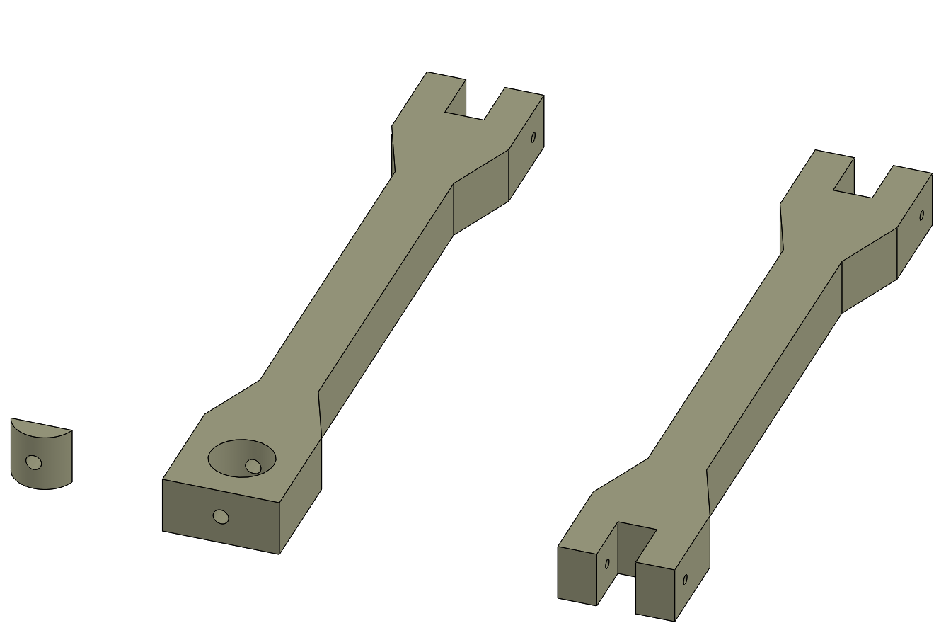
-
@Kolbi said in Battling sources of vibration and noise:
@Nxt-1 funny enough - I was thinking of a semi-rigid dog-bone linkage as well. The dog on the left would be for running a bolt up through the center with the nut on top of the insert, whereas the one on the right would be using a bolt's eye or similar.
Depending on available tools and materials, it may be much easier and faster to design hard ends (printed) with rubber attached between? I do remember making custom polyurethane bushings - maybe you could design a mold and do similar, that would be spot on.I fail to understand how your linkages work or are installed. I am not saying they don't work, I just not following what they do and how they fit in the machine in what orientation

To be honest they way I did it in the picture was just to verify that isolating the bearing would do the trick in terms of noise reduction. I was originally thinking of designing a bracket very similar to the printed one I was using previously, just with more room to accommodate a rubber bushing.
I literally just found a possible source for a rubber bushing in the size I need (12mm ID) but generally I have trouble sourcing these. So I started looking more into DIY solutions got some type B cylindrical vibration dampers from a local hardware store and drilled the threaded hole out to 12mm. What do you know, there is no metal left in the pocket, doh. (and M12 size dampers are way to large) See the right most thing on the picture
Next I got some type D cylindrical vibration dampers and with much struggle managed to make a 'hole' in the flat end where a bearing can fit in. I am not convinced this is the way to go as machining rubber is an absolute nightmare without stuff like dry ice to harden the rubber. That being said, doing it this way leaves me with two mounting options, one bushing style and one with the threads on either side. I'll continue to work on this and keep updating as I go


-
@Nxt-1 said in Battling sources of vibration and noise:
how your linkages work or are installed
Two different designs, one of left is for bolt / threaded rod attachment, one on right is for bolt that would have an 'eye' on it.
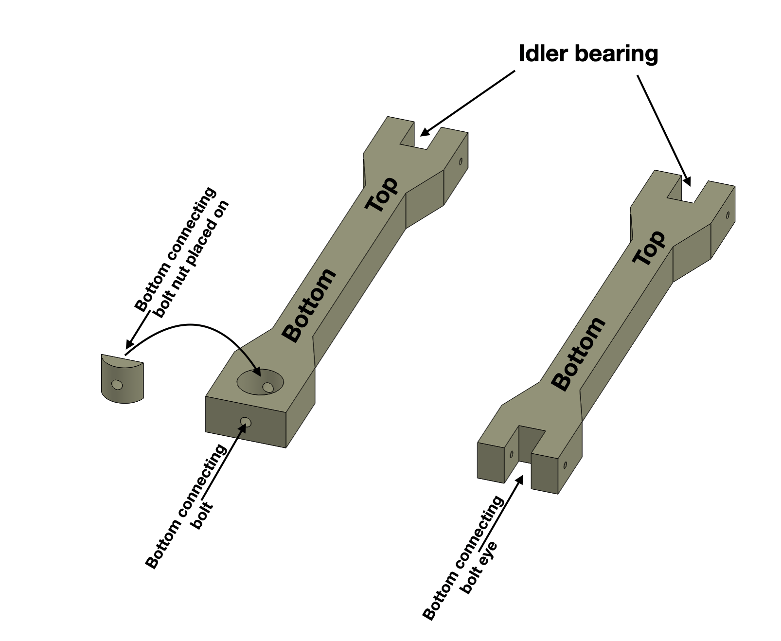
On casting polyurethane: https://youtu.be/gFJqBJleiVY
-
@Kolbi That explains it, I understand now.
I have no experience with polyurethane but most seem to dangle around 80 shore D, which seems way to stiff for use in a bushing like this. I expect it to inadequately isolate the vibrations. However casting a bushing myself might be a good idea, albeit from a softer material I'd say, something like a stiff silicone maybe 70 shore A or something.
-
@Nxt-1, from what I remember you can vary the mix to obtain the hardness desired. Guess it really depends on what type of kits are available in your area/shipping restrictions and such, and how it is designed. So if it is a stiffer material you could then 'thin' the connecting structure to allow absorption of the offending frequencies.
I have seen some formulas to help determine such but I think in the end, it really comes down to trial, error, error-correction, and then winning - but that's what makes the process fun and rewarding. Also remember that whatever material you choose to go with, it will be subjected to a heated environment and its properties may change - so do testing at room temp and again at the expected chamber temp. -
@Nxt-1 one option (though may be hard to implement) would be to use standard nitrile/nbr o-rings. They're usually about 70 shore A and you can get them in a range of sizes. Maybe have two on the OD of the bearing and a smaller one for it to butt up against axial?
-
@engikeneer That's a creative idea, I'll keep that in mind.
For now I just finished designing a revised bracket similar to what I had originally. It has gotten quite a bit wider to accommodate the two dampers but there is width-space available. Since doing the enclosure stuff I actually don't have a working printer at the moment so I'll get that sorted out first and we'll see from there.
