Black Beauty Arises!
-
I think the susceptibility to jamming of parallel rail systems can be large overcome with minimal loss of stiffness by using parallel flexures in one of the linear rail truck mounts. But only in a system with parallel driving on both linear ways such as CoreXY or twin ballscrew.
I tend to use the simplest and cheapest of IGUS products if at all, due to their attitude to precision. I like them for damping, silence and no need for lube. While other tribopolymer bearing developers like PBC have addressed imprecision of extrusions and heavywall moulded plastic bearing parts in various ways, IGUS resolutely isn't interested in precision plastic bearings combined with reasonable value for money. I had them in to visit with me recently in connection with tower bearings for a heated chamber Delta printer I'm involved with. While they have a range of tribo bearing materials that are rated for service up to 180C, the hard anodised aluminium rails themselves are not suitable for service with these grades, and steel tubes or shafts are needed to exploit them and get a reasonable wear life. I think the material you chose for your sliders is probably a general purpose grade they call J. That is OK to about 80-90 C and works very well with hard anodise.
I'm impressed by the implied quality of printing you can get even on v small TPU parts. Perhaps one reason for that is the relatively stiff structure of your machine, and the structural damping and absence of stick-slip provided by the IGUS bearings?
-
Updated XY Gantry
I went ahead and went back to an arrangement where the rails are laid horizontally. It's much easier to tune and results in a simpler, lower mass design.
Here's the right-side carriage:
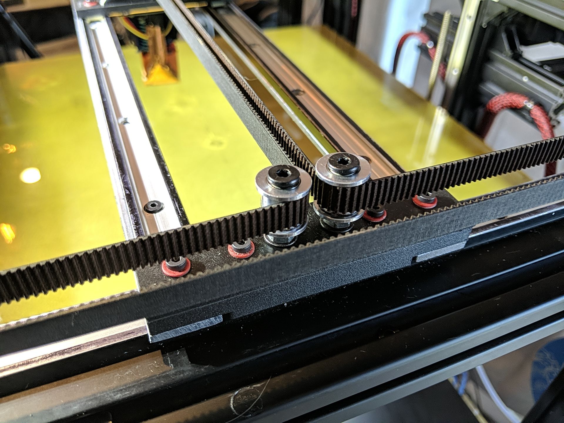
The pulleys are bolted to a piece of6(oops 3) mm aluminum which sits on top of a printed spacer. The 4 screws go through to the 30mm Igus sliders. The pulleys have to be offset from the carriage center line towards the inside by 0.375mm to make the belts co-linear and parallel. Since I'm lucky to get a tolerance of 3 mm with my cheap drill press and bad eyes, I printed templates then drilled through them to get the correct spacing.Left side:
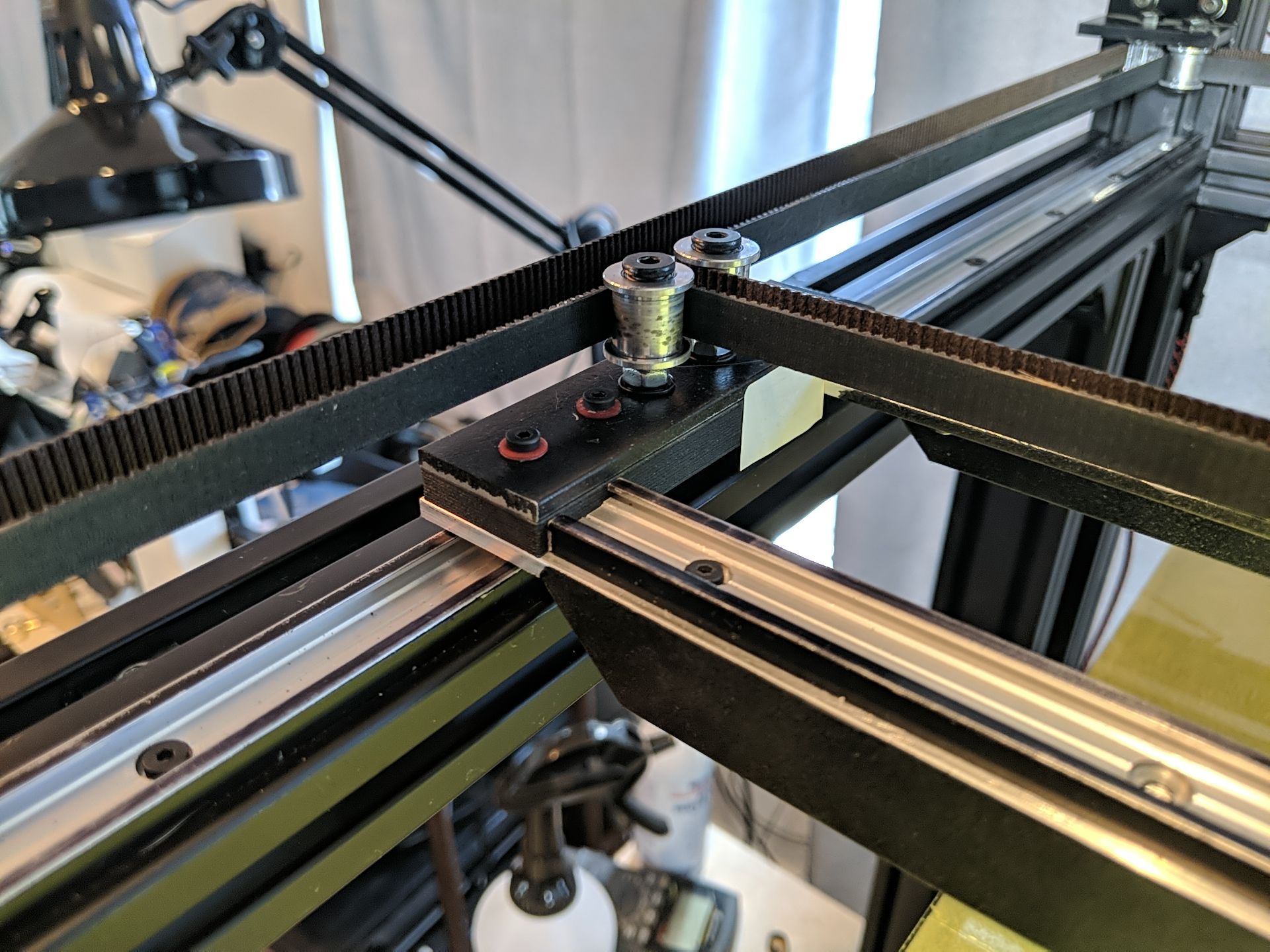
You can see the aluminum plate a little easier. The support truss extends all the way under the carriage.Center Carriage:
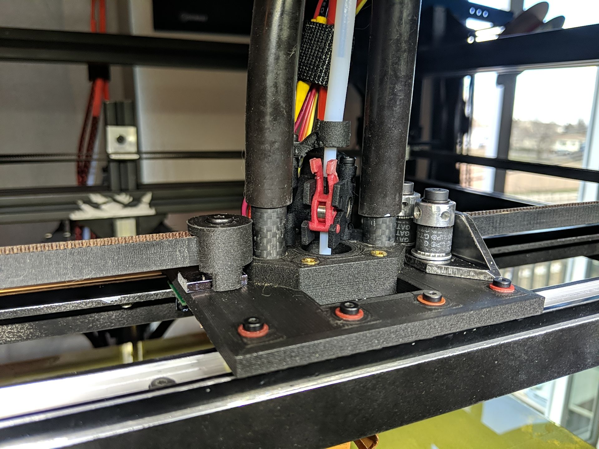
Now one piece instead of 4. As I said earlier, the belt is one long 4.68m piece. The center of the belt is fixed to the left side of the carriage by wrapping it around a toothed pulley which is clamped to the plate so it can't rotate or skip. The free ends of the belt come in from the right and wrap around 2 drive gears that are rotated until the belts are at proper and equal tension, then tightened down. Both the left and right attachments go through 6mm aluminum to spread the load.So without any real calibration, I printed 45 minutes of a 100mm test cube...
Corner View:
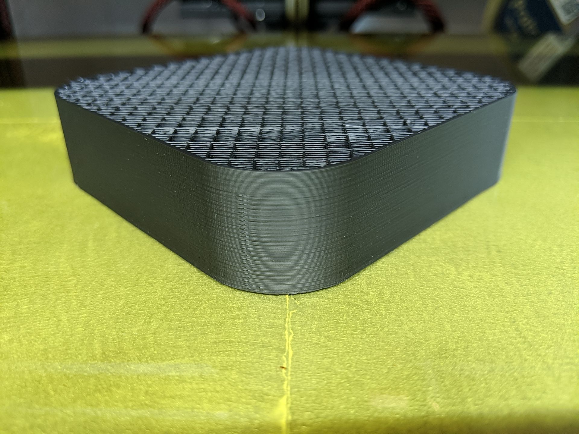
The artifacts at the start of the corners are due to my forgetting and leaving the "random" layer start point selected but you can also see some slight Z banding.Side View:
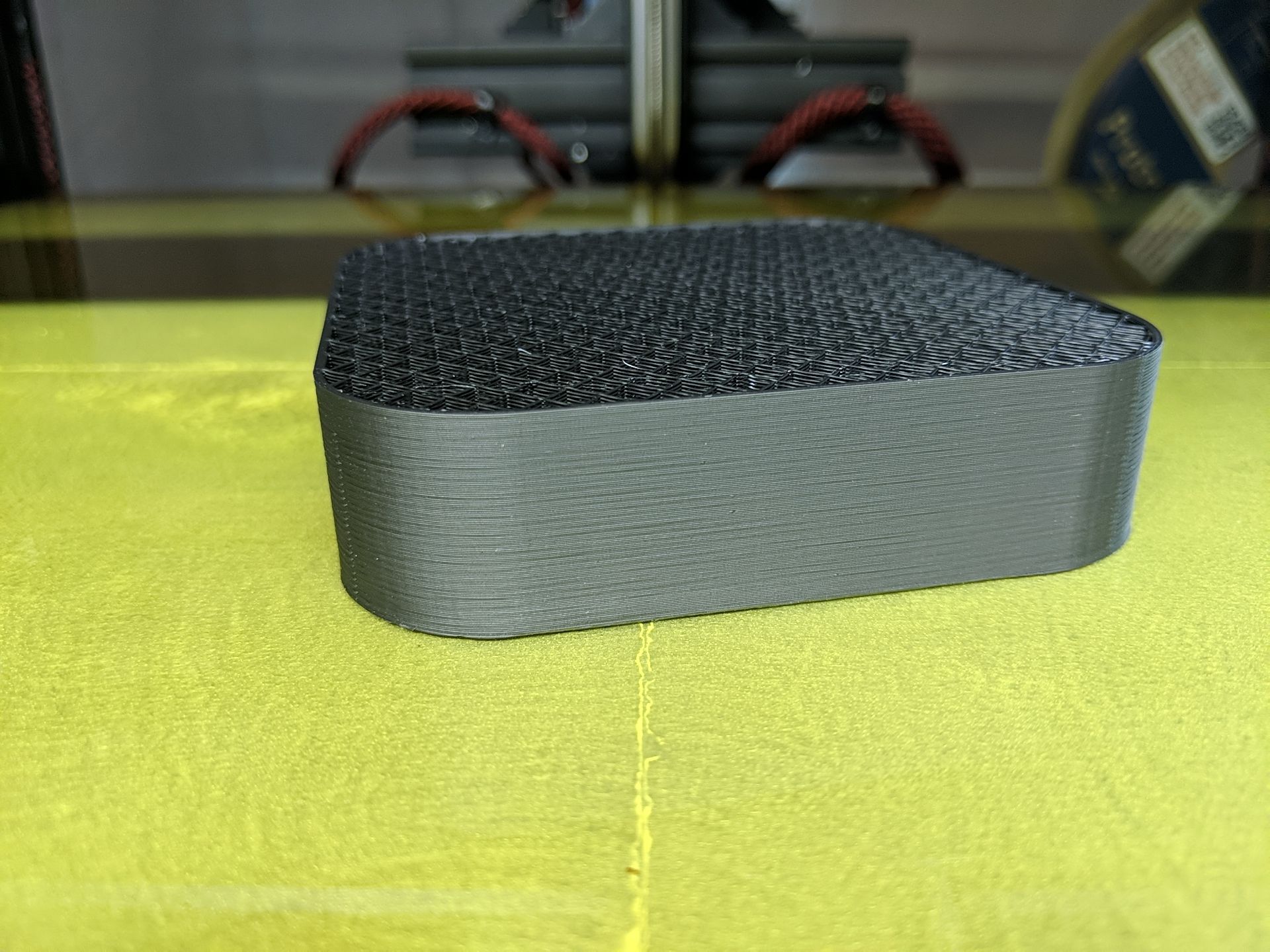
With a side view, you can see a little more banding but it's actually not bad. I had to look closely to see it with the naked eye.Back View:
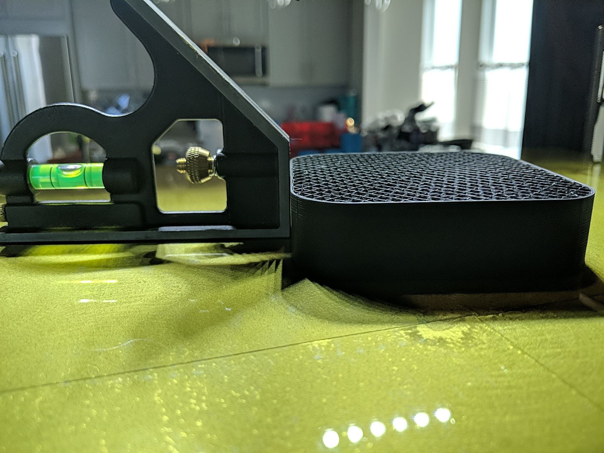
With the square butted up against the piece, you can see a slight gap that my feeler gauges say is about 0.06mm but it's on all 4 sides so it may be an artifact of the material shrinking and me not letting it cool evenly. There's a lot of surface are on the bottom and the PEI really grips it.Heightmap:
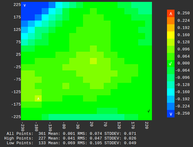
The heightmap looks pretty good. The dip in the back left corner is actually a deformation in the bed. The high point (0.106) is actually towards the front left (-180,-150) but it's a piece of something that got caught in the adhesive between the PEI and the bed surface.Next stop... A sharp cornered test cube and some real tuning.
-
Oh, I forgot to mention my heat treating setup...
Here's the center carriage plate vacuum pressed to a piece of borosilicate glass.

And surrounded by rice for better heat distribution.

Heated at 110C for 20 minutes then allowed to cool back to room temperature without opening the oven door..
Besides holding the piece flat, the vacuum seal also guards against moisture. Although the relative humidity is normally only in the teens here, I only have a gas oven and Methane + Oxygen = Carbon Dioxide + Water. Go figure.
-
Glad to see you're still working on your Black Beauty. I had been following you on the RR Forums when you still had the cross gantry setup.
As I'm currently trying to figure out where to go with my project and actually was leaning towards a cross gantry setup: what made you switch to CoreXY?!
-
Very nice!
-
@bberger said in Black Beauty Arises!:
Glad to see you're still working on your Black Beauty. I had been following you on the RR Forums when you still had the cross gantry setup.
Seems like an age ago.

As I'm currently trying to figure out where to go with my project and actually was leaning towards a cross gantry setup: what made you switch to CoreXY?!
The size of the printer places the nozzle right at my eye level, which I like, but with a true XY cartesian setup it also placed the front rail right in front of my face. It just got annoying. My design was also touchy to align and while it worked, a single tooth slip of a belt on a drive gear would result in a racked gantry. I'm not sorry I tried it by any means. I learned so much during the process.
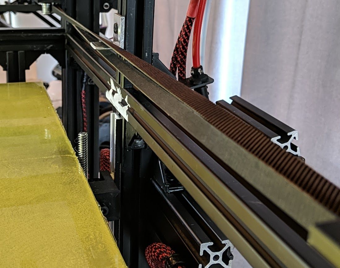
The thing about CoreXY that I didn't like that started me down the cartesian XY route in the first place was the belts on multiple planes and the complexity of the routing. Also in my case, the 2 belts would each be over 2m long and I was worried about stretching. @mrehorstdmd's excellent forum and blog posts got me thinking again though and with the realization that, with the 600mm X span, I could use a belt twist at the back to keep the belts on the same plane without putting undue stress on them, I finally figured I'd give it a shot. I'm happy I did. I can now see the nozzle/print clearly and it's just not possible for the gantry to rack. It's also 2 less motors.
 The move to genuine Gates 9mm wide belts eliminated my concerns about stretching.
 -
I think that if you twisted the belts so that the smooth back sides were dragging on the separator you be less likely to wear the toothed sides of the belts and less likely to induce bumps in your prints from the teeth hitting the separator. At high speeds there is probably a zip-zip sound coming from the separator. That will go away if the smooth backs of the belts touch it instead of the teeth.
-
@mrehorstdmd The spacer is polished and the leading and trailing edges are tapered so I don't hear anything. I thought I tried with the smooth sides facing each other but for some reason I couldn't make the routing work. Maybe I was just being an idiot. I can't see it in my mind so I'll have to actually try it which I can do later today.
-
@mrehorstdmd O Wise Dentist... it don't work.
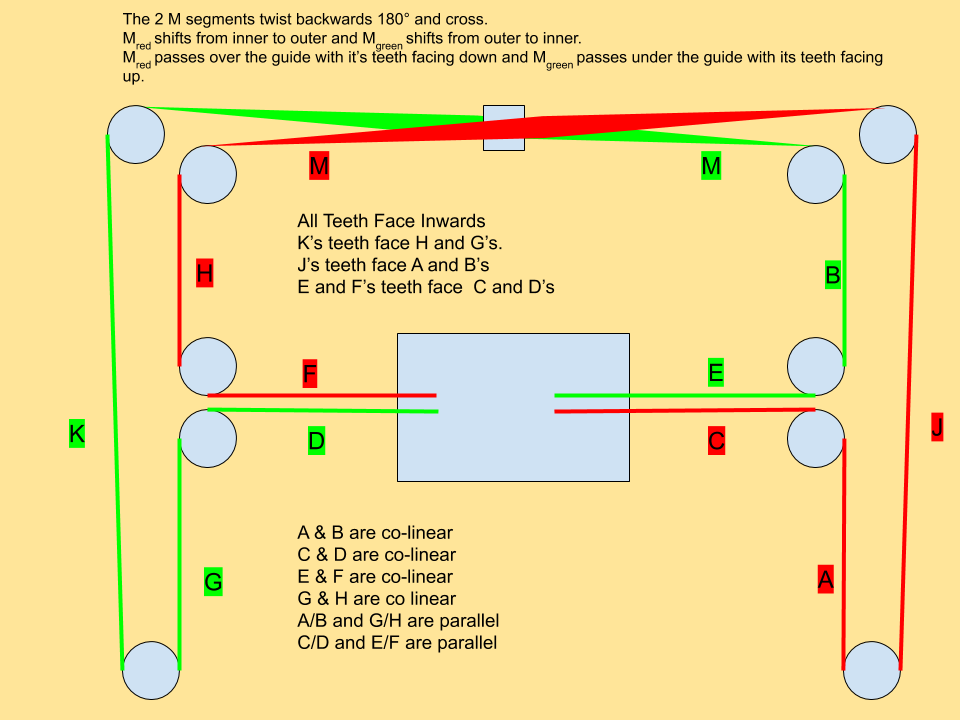
I cannot figure out any routing that will allow the 2 M segments to cross with their smooth surfaces facing each other unless I separate the segments vertically at the center guide. That however, makes the belts interface with the idlers at too great an angle for my taste.
Got any ideas???
-
@gtj0 How about making the top belt the bottom belt and the bottom belt the top belt at the crossing point?
-
@mrehorstdmd I meant to upload this pic earlier...
If I just swap the belt positions, they rub against each other. I'd either have to separate the belts vertically at the center which cause the idler interface angle to increase, or I'd have to move the 2 "inner" corner idlers more towards the front eating up Y travel.
I suppose I could also try adding 2 more spacer/guides at the 1/4 points but that just makes things more complicated and I'd think also increase friction beyond what would be saved by having the smooth sides face each other at the center.
-
I had used coplanar belts in my sandtable and after looking at your pictures and diagram I couldn't figure out why you couldn't get it to work. Then I realized that I had put the twists in the J and K segments on your diagram so that the smooth surface of the belt rode on the smooth outer corner pulleys. You're twisting and crossing at the same location. That's the problem.
-
@mrehorstdmd Hmmm. I tried that but maybe I didn't follow it all the way through. I just started a full 441 point bed probe so maybe i'll try that again in the morning. Thanks!
-
Is this what you meant? A twist on the sides as well as the back?
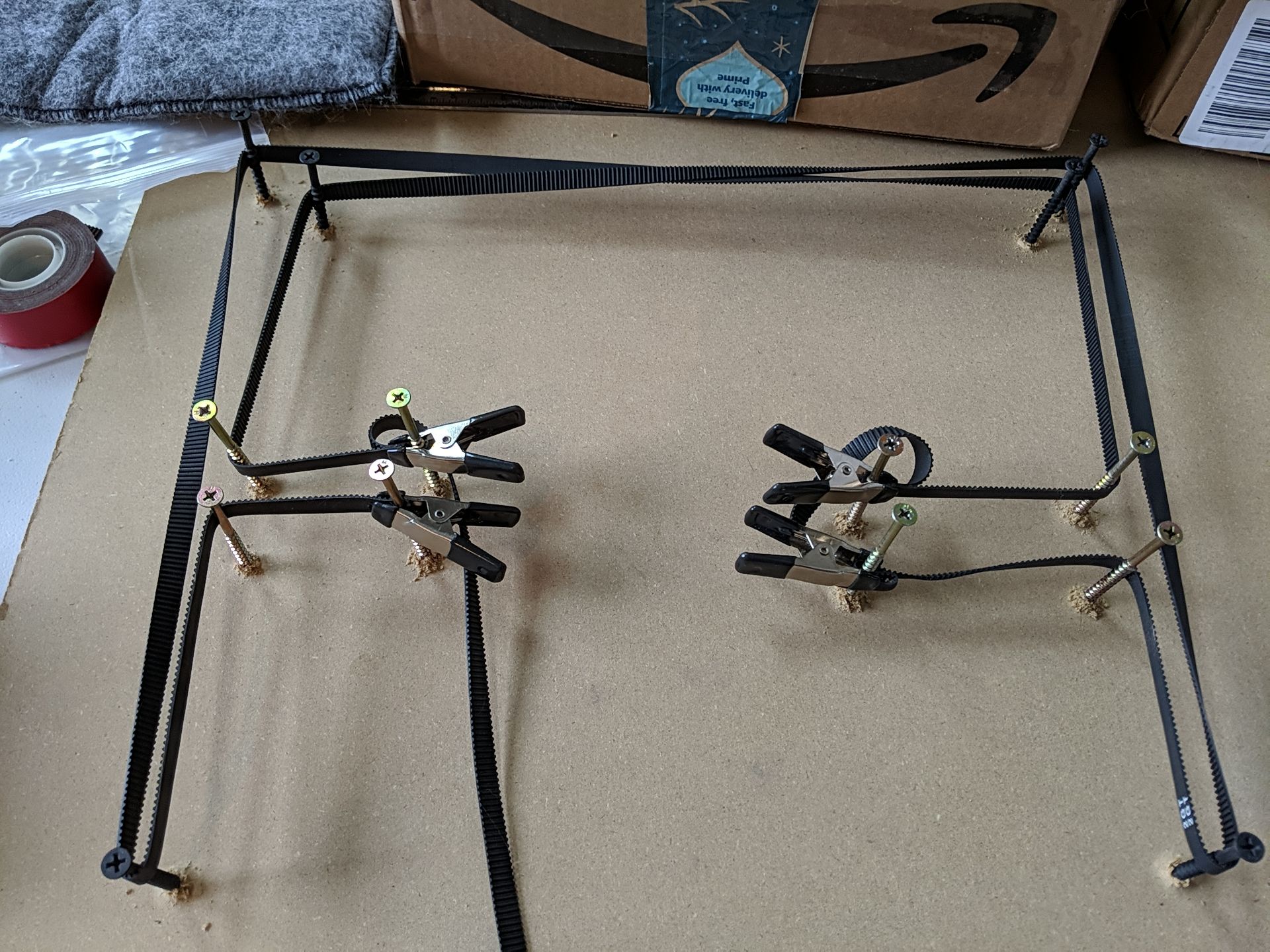
Or this? The "M" segments aren't twisted any more but they have to be deflected so they can pass by each other and the deflection isn't "natural" so there'd be uneven wear against a spacer.
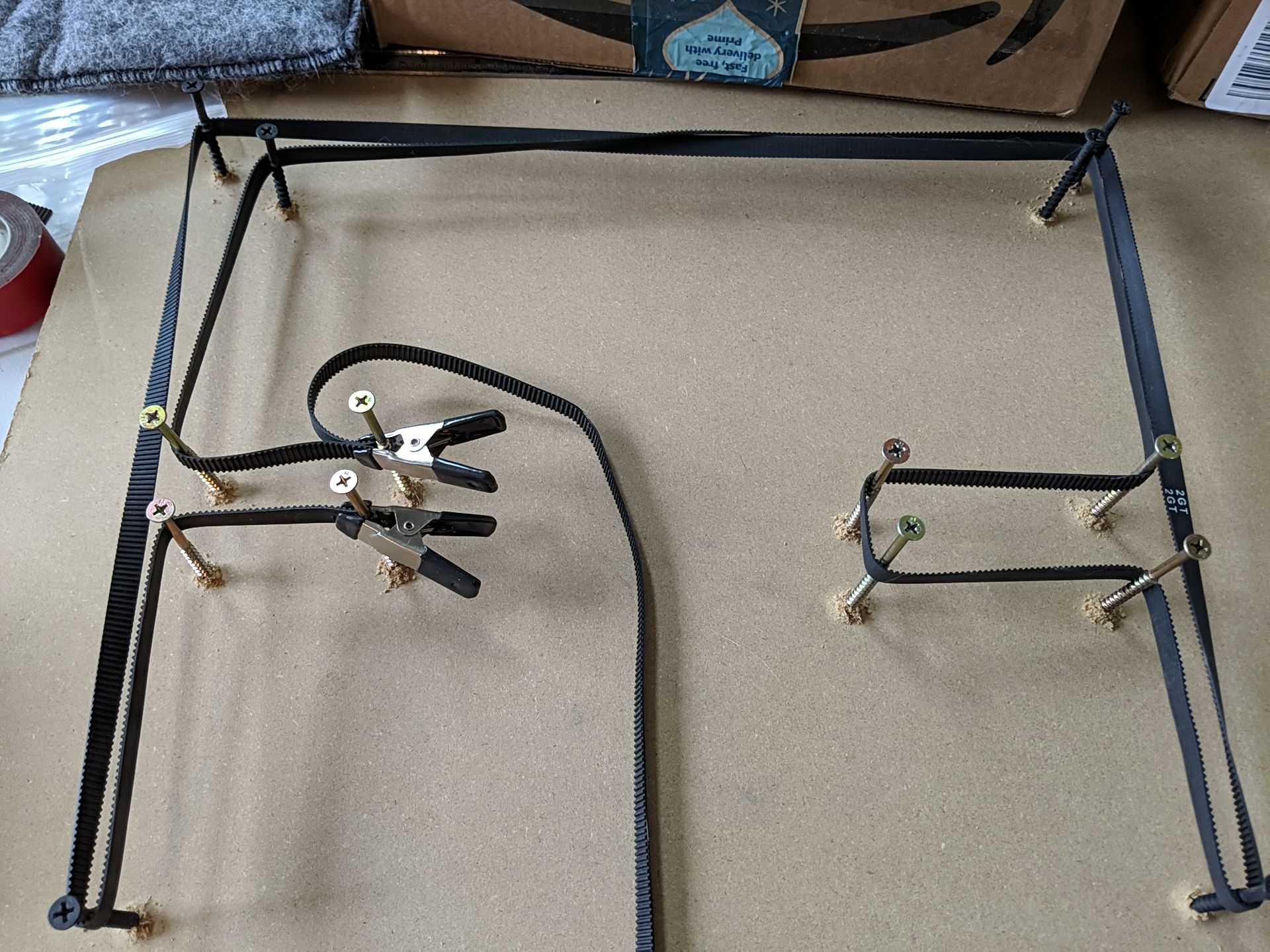
Either way seems overly complex.
I think I'm going to stick with what I've got and watch it. I can always add toothed idlers at the crossover point if I need to.
-
@gtj0 Not quite sure, but in my setup, the only pulleys that the belt teeth contacted were the drive pulleys. It might be that the belts have to be twisted in opposite directions. The table is so big there isn't any one photo that shows the whole belt layout. Let me see if I have some other photos that will reveal how it was done.
-
Sorry for quickly derailing the Belt Routing discussion..
However: what made you go with Igus N over the Igus W? The W kind of looks a lot more stable.
-
@bberger said in Black Beauty Arises!:
Sorry for quickly derailing the Belt Routing discussion..
However: what made you go with Igus N over the Igus W? The W kind of looks a lot more stable.
No worries! They were simply too big both in size and mass for what I wanted.
-
@gtj0 how about use a GT2 Idler Pulley without teeth?
-
@gtj0 this may seem like an odd question, but it's one thing that's been actually bugging me:
How would you rate the noise levels of especially the belt paths between your cross gantry and corexy build?I'll get a demo rail of the 40x40 drylinN hopefully at Tuesday and if that actually works out on my Delta I may be ready to dive into an actual full Igus build..
I've been happily using Igus stuff for a decade now in various (non printer) projects and I've admittedly become a fan of their stuff and to be frank - right now I don't care if they can match Hiwin/TSK/IKO/etc precision. It's readily available to me, I can get it fast and for a reasonable enough price to just tinker with it. If it fails I'll just repurpose the stuff.Right now I'm just after an as-silent-as-possible printer that doesn't have to print at insane speeds. (as long as it can run overnight in our open living room I'm good). You've actually pulled off 2 different working gantry designs off Igus rails - that's good enough for me for now.
That leaves me with basically 2 concerns:
- noise from the belt
- noise from the motors themselves
The plastic stuff should be good at dampening vibrations, so that's an added bonus.
I don't really care about cost too much on that build and I'm still undecided between going Makerbot gantry with dual Y motors (stealthchop2 on Moons motors) or corexy. I'm not looking at crazy acceleration or jerk values and if it's silent then I have no problem with it going 2 nights instead of one..
Long story short:
- does anybody feel the long belt path of CoreXY adds additional noise from the belts over a cartesian/crossgantry design?
- I'd appreciate ANY tips/insights on Igus rails. Orientation, preload, number of carriages, anything to get me a headstart.
You're the single one person I know as of yet that pulled off an Igus based printer. I want to suck up any knowledge that you're willing to share

-
@bberger said in Black Beauty Arises!:
does anybody feel the long belt path of CoreXY adds additional noise from the belts over a cartesian/crossgantry design?
Maybe if you're really going fast there can be a bit of a zip zip zip sound, but at tame speeds it's quite silent for me.