Printed bolt threads are wrong direction CoreXY
-
I don't know why, but every profile I've ever seen of S3D needed to have "Flip build table" checked for Y axis.
As you can see, the Y axis is positive towards the front from th eback.
Check the Flip build table Y axis and see if it's correct.
-
-
I am completely lost on it...
Can somebody have a look, please? Now If I do home all everything goes in the right direction. but then X hits a switch it doesn't go back anymore 3mm to make a soft home. And X-axis doesn`t move after home. If I switch M574 X1 S0 to M574 X1 S1 than X-axis not even trying to move at all for homing. Can somebody guide me through the right process? I checked all links from the wiki, but now it seems I am just more confused as I have no idea if I needed to switch motors wiring or not? Even tho at really beginning I did movement test and everything works well but was printing mirrored anyway.
config.g
; Configuration file for Duet WiFi (firmware version 2.03)
; executed by the firmware on start-up
;
; generated by RepRapFirmware Configuration Tool v2.1.4 on Thu Jan 02 2020 22:17:48 GMT+0100 (Central European Standard Time)

; General preferences
G90                                             ; send absolute coordinates...
M83                                             ; ...but relative extruder moves
M550 P"own"                                     ; set printer name

M667 S1                                         ; select CoreXY mode

; Network
M552 S1                                         ; enable network
M586 P0 S1                                      ; enable HTTP
M586 P1 S0                                      ; disable FTP
M586 P2 S0                                      ; disable Telnet

; Drives
M569 P0 S0                                      ; physical drive 0 goes forwards
M569 P1 S0                                      ; physical drive 1 goes forwards
M569 P2 S1                                      ; physical drive 2 goes forwards
M569 P3 S0                                      ; physical drive 3 goes backwards
M569 P4 S1                                      ; physical drive 4 goes forwards
M584 X0 Y1 Z2 E3:4                              ; set drive mapping
M350 X16 Y16 Z16 E16:16 I1                      ; configure microstepping with interpolation
M92 X201.207 Y201.207 Z400.00 E415:415		; set steps per mm
M566 X1200 Y1200 Z400 E1500.00:1500.00      	; set maximum instantaneous speed changes (mm/min)
M203 X10000 Y10000.00 Z600 E10000.00:10000.00   ; set maximum speeds (mm/min)
M201 X800 Y800 Z400 E4000.00:4000.00      	; set accelerations (mm/s^2)
M906 X1200 Y1200 Z1300 E700:700 I30               ; set motor currents (mA) and motor idle factor in per cent
M84 S90                                         ; Set idle timeout
;M572 D0:1 S1.5:1.5				; Pressure advance

; Axis Limits
M208 X-12 Y-5 Z0 S1                                ; set axis minima
M208 X316 Y267.5 Z334 S0                        ; set axis maxima

; Endstops
M574 Z1 S2                     ; set active low and disabled endstops
M574 X1 S0                  ; set active high endstops
M574 Y2 S0

; Z-Probe
M307 H3 A-1 C-1 D-1                             ; disable heater on PWM channel for BLTouch
M558 P9 H5 F300 T15000                          ; set Z probe type to bltouch and the dive height + speeds
G31 P500 X-10 Y-51.5 Z0.82                            ; set Z probe trigger value, offset and trigger height
M557 X0:290 Y0:250 S15                      ; define mesh grid

; Heaters
M140 H-1                                        ; disable heated bed
M305 P1 X200                                    ; configure PT100 for heater 1
M143 H1 S450                                    ; set temperature limit for heater 1 to 450C
M305 P2 X201                                    ; configure PT100 for heater 2
M143 H2 S450                                    ; set temperature limit for heater 2 to 450C

; Fans
M106 P0 S0 I0 F500 H-1                          ; set fan 0 value, PWM signal inversion and frequency. Thermostatic control is turned off
M106 P1 S1 I0 F500 H-1                          ; set fan 1 value, PWM signal inversion and frequency. Thermostatic control is turned off
M106 P2 S1 I0 F500 H-1                          ; set fan 2 value, PWM signal inversion and frequency. Thermostatic control is turned off

; Tools
M563 P0 S"Left" D0 H1 F-1                       ; define tool 0
G10 P0 X0 Y0 Z0                                 ; set tool 0 axis offsets
G10 P0 S0 R0 				; Set tool 0 active and standby temperatures
M563 P1 S"Right" D1 H2 F-1                      ; define tool 1
G10 P1 X20 Y0 Z0                                 ; set tool 1 axis offsets
G10 P1 S0 R0 				; Set tool 0 active and standby temperatures

; Custom settings are not defined

; Miscellaneous
M501                                            ; load saved parameters from non-volatile memory
; homex.g ; called to home the X axis G91 ; relative positioning M913 X50 ; set X motors to 50% of their normal current for homing G1 S1 X321 F1000 ; move quickly to X axis endstop and stop there (first pass) G1 X-3 F1000 ; go back a few mm G1 S1 X321 F200 ; move slowly to X axis endstop once more (second pass) M913 X100 ; set X motors to 100% of their normal current; homey.g ; called to home the Y axis G91 ; relative positioning M913 Y50 ; set Y motors to 50% of their normal current for homing G1 S1 Y272.5 F1000 ; move quickly to Y axis endstop and stop there (first pass) G1 Y-3 F1000 ; go back a few mm G1 S1 Y272.5 F200 ; move slowly to Y axis endstop once more (second pass) M913 Y100 ; set Y motors to 100% of their normal current; homeall.g ; called to home all axes ; Home XY for Z homing ; G91 ; relative positioning M913 X50 Y50 ; set X Y motors to 50% of their normal current for homing G1 S1 X-321 Y272.5 F1000 ; course home X or Y G1 S1 X-321 F1000 ; course home X G1 S1 Y272.5 F1000 ; course home Y G1 X2 Y-3 F1000 ; move away from the endstops G1 S1 X-321 F200 ; fine home X G1 S1 Y272.5 F200 ; fine home Y M913 X100 Y100 ; set X Y motors to 100% of their normal current ; Z homing section follows ; G90 ; absolute positioning G1 X158 Y108 F1000 ; Move x and Y axis over to bed center so probe is on top of bed ; Set lower speeds for homing M566 Z5 ; Set maximum instantaneous speed changes (mm/min) (Jerk) M203 Z400 ; Set maximum speeds (mm/min) M201 Z100 ; Set maximum accelerations (mm/s^2) ; Probe the bed ; M558 A1 F350 ; Set single probing at faster feed rate G30 ; Do a single probe to home our Z axis M558 A10 F100 ; Set tripple probing at slower feed rate G30 ; Probe again to get a more accurate position ; Set normal speeds again M566 Z400 ; Set maximum instantaneous speed changes (mm/min) (Jerk) M203 Z600 ; Set maximum speeds (mm/min) M201 Z400 ; Set maximum accelerations (mm/s^2) ; Move X and Y back Home ; G1 X0 Y272.5 -
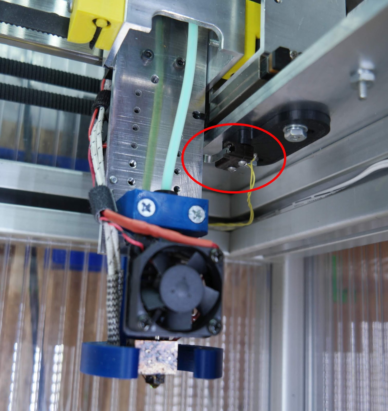
Can you post a photo of your printer from the front and indicate where the endstops are located?
-
Hi @Phaedrux
There is it, with X and Y switches visible
 85-b760db5b-d95c-4482-9c5c-d45afe2a507f-resized.jpeg)

-

-
It looks to me like you have the homing switches in the right rear corner of the machine, and the motors at the front of the machine. The A motor is on the left (plugged into the X diver on the Duet board) and the B motor is on the right (plugged into the Y driver on the Duet board), the same way I set up my printer (except that I put the X switch on the printer's frame instead of on the extruder carriage). I have the origin set to the center of the bed. Here is the relevant section of my config.g file:
; Drives
M569 P0 S1                                ; motor A goes forwards
M569 P1 S0                                ; motor B goes backwards
M569 P2 S1                                ; Z motor goes forwards
M569 P3 S1                                ; extruder motor goes forwards
M350 X16 Y16 Z16 E16 I1                   ; Configure microstepping with interpolation
M92 X160 Y160 Z800 E411                   ; Set steps per mm
M906 X1600 Y1600 Z1120 E500 I30           ; Set motor currents (mA) and motor idle factor in per cent
M84 S30                                   ; Set idle timeout

M205 X20 Y20 Z2 E50                       ; Set maximum instantaneous speed changes (mm/sec)
M203 X18000 Y18000 Z900 E3000             ; Set maximum speeds (mm/min)
M201 X3000 Y3000 Z1000 E3000              ; Set maximum accelerations (mm/s^2)
M204 P3000 T3000			  ; Set print and travel acclerations (mm/s^2)

; Axis Limits
M208 X-153:153 Y-178:150 Z0:687           ; Set axis minima:maxima

; Endstops
M574 X2 Y2 Z1 S1                          ; Set active high endstops
When homing, the extruder carriage should move toward the switches, regardless of their positions relative to minimum or maximum ends of the axes. M574 statement tells the machine that when the switches are activated, they are at Xmax and Ymax. The M208 statement tells the firmware what the ordinate values are at those positions.
-
Sorry, I got distracted by baby. Here's the post I started earlier in case @mrehorstdmd post didn't get you sorted.

Ok, so -X moves to the left, +X moves to the right, +Y moves to the back, -Y moves to the front. 0,0 is at the front left and 200,200 (for example) is back right.
You have the x endstop on the low end of travel (looks like its on the left side of the extruder carriage and the trigger bolt on the left side) and the Y endstop at the high end of travel at the back. The endstops look like makerbot style switches with an activation LED on the PCB, so active low.
M574 X1 S0
M574 Y2 S0Then in your homex you need to change from moving to X positive to X negative, like so:
; homex.g
; called to home the X axis

G91               		; relative positioning
M913 X50	 		; set X motors to 50% of their normal current for homing
G1 S1 X-321 F1000 		; move quickly to X axis endstop and stop there (first pass)
G1 X3 F1000       		; go back a few mm
G1 S1 X-321 F200  		; move slowly to X axis endstop once more (second pass)
M913 X100	 		; set X motors to 100% of their normal current
Home Y looks correct.
Homeall looks correct as well.
If the head isn't moving in the direction you expect (like -X going to the right) then one of the motors is either plugged into the wrong motor port, or needs to be reversed. Note your motor connections as described by mrehorst, and use the motor direction test from the corexy setup link to verify that the motors are turning in the right direction.
-
Damn! Thank you guys a million!
That was making me nuts... Eventually, I needed to swap motors indeed and reverse them:M569 P0 S1 ; physical drive 0 goes forwards M569 P1 S1 ; physical drive 1 goes forwards@Phaedrux thanks a lot for a sketch and tweaking the homex.g - that solved it all.
Minus one issue - million to go :))
-
@felt342 Good! Now you can get to the fun stuff like calibrating the extruder...
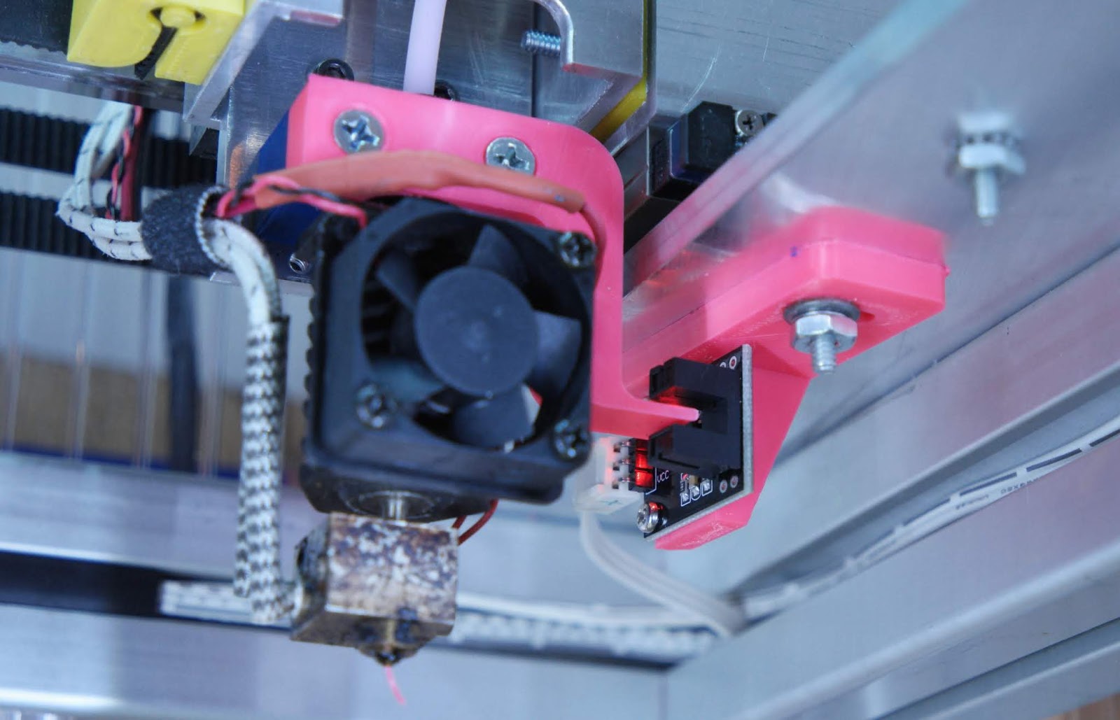
It isn't entirely necessary to have the X endstop on the X axis. Doing so requires an extra wire or two going to the extruder carriage. I prefer to minimize wires going to the extruder carriage. You can put the X axis endstop on the printer's frame instead, in which case you'll have to home Y before homing X. I've been doing that in my printer for over a year and it works fine. I just modified the homex.g file to home Y before it homes X.Older version of extruder carriage with X endstop mounted on printer frame:

Latest version:

-
It is a good point, I am thinking about to stick it to the frame. May I ask you that tunnel switch, is there any advantage compared to normal switch?
-
Well it is occasionally handy to be able to home the X axis without having to first home the Y axis to get it in position.
-
@Phaedrux said in Printed bolt threads are wrong direction CoreXY:
Well it is occasionally handy to be able to home the X axis without having to first home the Y axis to get it in position.
Before I put the switch on the frame I thought the same thing. In the year or so that it's been that way I haven't missed being able to home the X axis independent of Y.
-
@felt342 said in Printed bolt threads are wrong direction CoreXY:
It is a good point, I am thinking about to stick it to the frame. May I ask you that tunnel switch, is there any advantage compared to normal switch?
I assume you're referring to the optical switch. The ones I used have an LED on board that indicates when the light is blocked and that can be handy for making adjustments without having to check the display connected to the controller board. The type of snap action switches I was using always have some hysteresis that can make adjustments a little tricky, especially setting the Z=0 position in my sensorless printer. The optical switches have much less hysteresis. I'll be converting the Z axis endstop in my printer to optical next, now that I have figured out a way to make very fine adjustments.
I'm have mixed feelings about the optical endstops. The snap action switches I was using are extremely reliable. I don't know how well the optical switches will hold up at 50C. I haven't done any testing to see if the switches are affected by ambient light. These type of things are used in industrial machinery all the time so it's probably not an issue.
-
Thanks for sharing your experience!


