Programming a smart effector
-
To continue this, several months later. I finally got around to building a second one. Unfortunately neither of them seem to work. I am able to program them, avrdude recognizes them as attiny44s, but the status light never comes on, and the probe seems to trigger somewhat randomly. Any ideas on troubleshooting? Everything else works fine, all the other lights light up, the only issue is probing. Both boards seem to have this issue.
-
@curieos said in Programming a smart effector:
To continue this, several months later. I finally got around to building a second one. Unfortunately neither of them seem to work. I am able to program them, avrdude recognizes them as attiny44s, but the status light never comes on, and the probe seems to trigger somewhat randomly. Any ideas on troubleshooting? Everything else works fine, all the other lights light up, the only issue is probing. Both boards seem to have this issue.
If the green trigger LED never comes on, I suggest you sort that out first. Check that it is fitted the right way round and the value of the series resistor is correct. Also, make sure you are using the correct firmware version - there are different firmwares for the version 1 and version 2 effectors.
-
@dc42 can you tell me the part number for the Attiny44a on ver 2.0
-
It's the 4mmx4mm version of the chip, which is attiny44a-mu.
-
@dc42 how do i programming the attiny44a already attached to smarteffector?
-

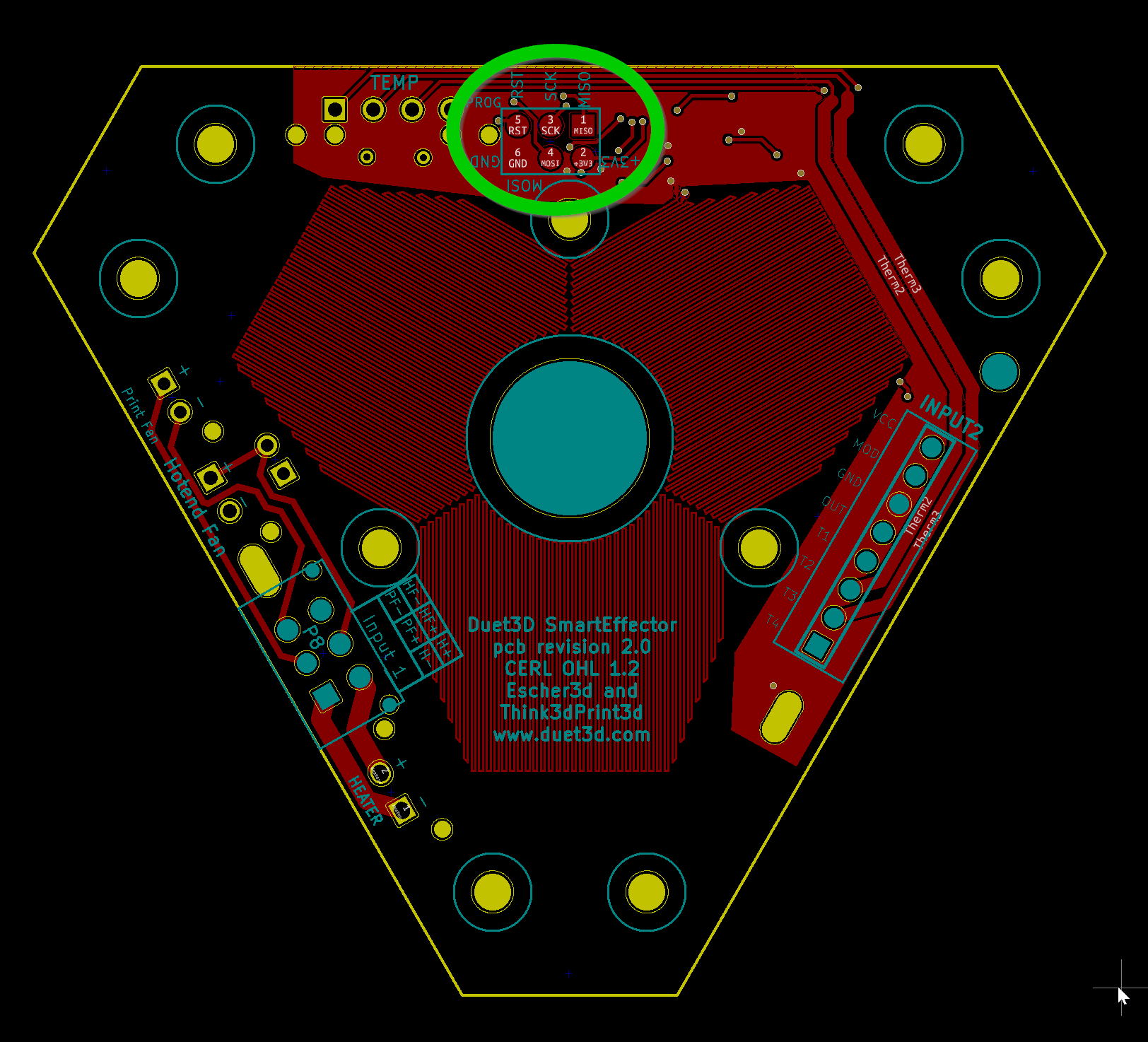
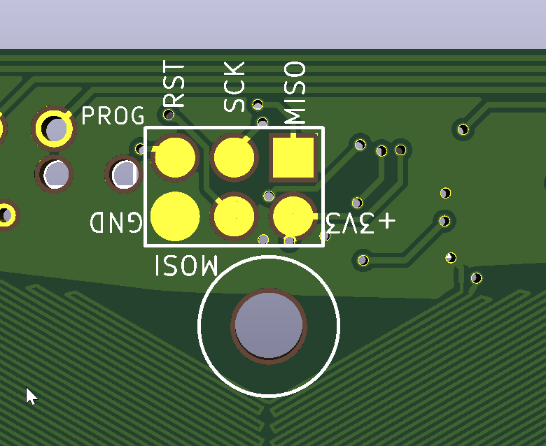
there should be a 6 pin header "prog"Looks to be smd pads, so you'll have to use pogo pins or solder wires to the pads and use an avr programmer with atmel studio etc (you might get away with holding a non spring loaded header to the pads, but chances are its not a success)
edit: whoa, missing linebreak
-
Use https://hackaday.io/project/165027-avr-isp-pogo-pin-adapters or https://www.sparkfun.com/products/11591 or https://www.amazon.com/pin-AVR-ICSP-Pogo-Adapter/dp/B075Q25BK3 or similar to make the connections (search for "avr pogo" to find more). Or make your own as i did.
-
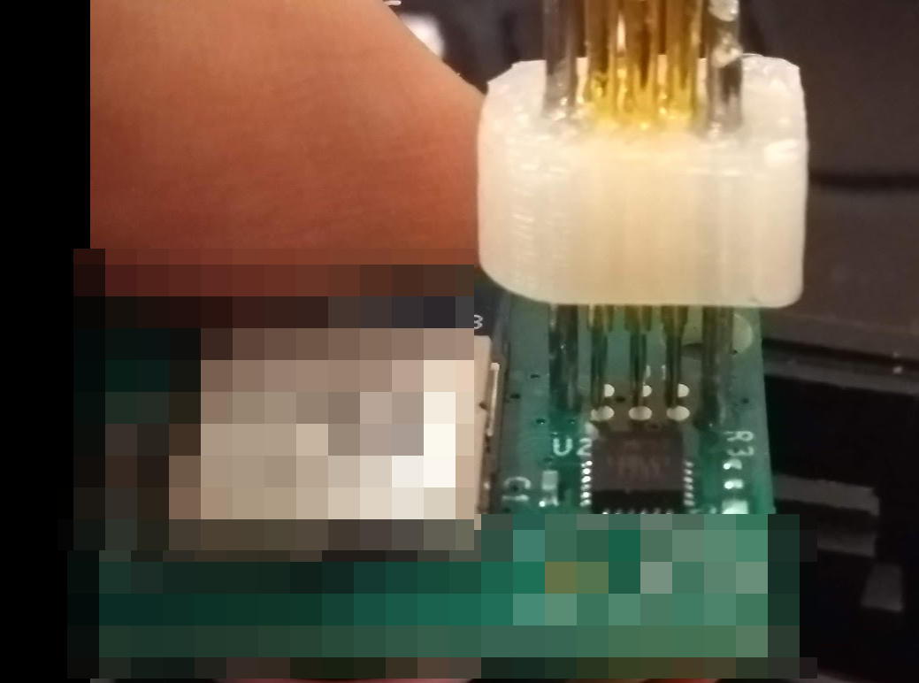
or you could buy a bag of pins and print a holder; i managed to replicte the tc2030 tag connect recently with some 0.75 or 0.5mm pins and spring steel wire for the guide pins.

if you get 1mm pins you can get receptacles with square posts that fit into the regular 2.54mm female idc, for that I just put he pins in the female header and squirted some hotglue on them while aligned but don't think i have a picture of that. never know when you'll need pins for something else.
-
I used very short pogo pins soldered directly to a 2x3 header.
-
Thanks all for the tips. unfortunately i am using mac, any recomendation for amtel studio alternative.
-
@ken340 said in Programming a smart effector:
Thanks all for the tips. unfortunately i am using mac, any recomendation for amtel studio alternative.
i think avrdude is available on most platforms and will work with pretty much any programmer. but you'll need to get a precompiled hex which i think dc42 has posted a link to here somewhere oin one of the old threads.
-
@bearer great, i saw dc42 hex file on his github
-
The 3.3V from the pin will power the smart effector? how do i know it is connected correctly?
will those cheap USBasp work?
-
@ken340 said in Programming a smart effector:
will those cheap USBasp work?
thats a lottery, at least when using them with windows. using yet another programmer to reprogram the usbasp clone could be necessary, and you'll most likely be banging your head in some issues with drivers.
i'd generally recommend against it maybe you can refrence this post in case you have something else on hand that you can use already?
https://forum.duet3d.com/topic/15661/chip-burned-i-need-a-new-one?_=1597701384110there is a bit more learning curve to getting an arduino pro mini + ftdi board, but it'll be much more versatile in the long run.
when it comes to 3.3v, make sure the programmer is also running of 3.3v to avoid 5v logic signals. the simplest test is to look at the wiring diagram and before turning on the power use a multimeter in continuity mode measure from 3.3v on the programmer to 3.3v on the target, repeat for ground, and round of checking there is no continuity between 3.3v and ground.
-
The Smart Effector can be programmed at either 3.3V or 5V, provided that is it not connected to a Duet at the time.
-
@bearer are they any way to know the pins are correctly connected. such as LED light up or something?
-
isn't the board clearly marked like so:

? -
This post is deleted! -
@uvarovkv i did not make my own smart effector. i am trying on my purchased smarteffector. since productivity is low at work due to COVID-19 so i am taking time to learn more about this little marvel.
when i connect 6 pogo pins to my smart effector without any power from duet. i am not getting my response from AVRdude using USBASP.
therefore i am not sure whether i am not connecting via pogo pins correctly or my USBASP is not working well (I use it to program arduino without issue) .
can you tell me with your connection to smarteffector for programming, do you get any physical indication like any LED is turned on? or there are no physical indication to tell the connection is good.
-
if the leds come on when you power the smart effector from the duet then they should come on when you power it from the programmer as well. if the leds need running firmware to come on then your milage will vary.