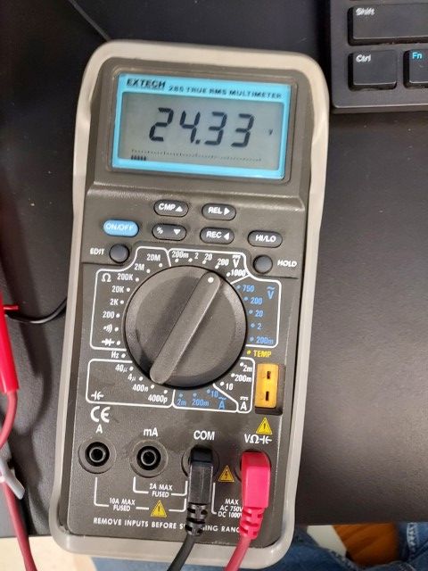
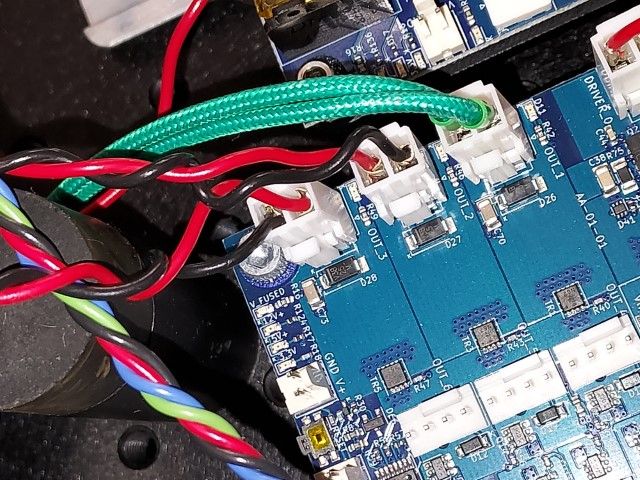
`Duet 6HC Output 3 output always on
-
Hello,
I am a researcher looking to use the Duet chip family to build some niche application machines. To that end, I am using a Duet 6HC and 3HC expansion for a custom machine in my lab. My team and I are attempting to use a solenoid defined with M950 as a "Fan" type device (the solenoid in question is a 24V 4.8W DC) on output pin 3 (we ordered a 12V and 24V solenoid, but the 12V was used elsewhere); I am new to electronics, but given the solenoid is DC, I thought setting the Q parameter to 0 would enable simple control of the solenoid with DC voltage instead of PWM control.
Prior to today, we had run the solenoid with "M106 ... Q500 X.3" command and had no issues getting it to trigger, but wanted to ensure we were operating the solenoid properly for long term operation before moving on to the next task (again, assuming that the proper way to drive the solenoid was not with PWM).
After setting the Q parameter to 0, I attempted to run the above M106 command. The solenoid opened and stayed active, but attempting to turn off the "fan" with M106 shutoff command no longer works. Looking at the output of Output 3 with a multimeter now shows that 24V DC current is being outputted from the Output 3 pins.My current thought is that the something has happened on the board that now causes it to only output 24V DC instead of on/off PWM. Given the mismatch between the usual 12V output and the 24V of the solenoid, I suspect that too much power was returned to the solenoid and a safety componet was tripped. Looking at the 6HC pinmap
I believe the "V_fuse" has been blown and is now freely allowing 12V passed through the pins, but this is only my thoughts and could very well be wrong.Can anyone direct me to more resources or ideas on how to fix the Output 3 voltage coming out? I have tried to look for where V_fuse is located, but have not had much success looking online. Visual inspection of my fuses seems to indicate no failures from what I can see, but direct testing the connections is next.
Here is my config.g file, with the "fan"/solenoid in question being defined as the M950 "out3" line
; Configuration file for Duet 3 MB 6HC (firmware version 3.3) ; executed by the firmware on start-up ; ; generated by RepRapFirmware Configuration Tool v3.4.0 on Fri Dec 29 2023 12:02:51 GMT-0700 (Mountain Standard Time) ; General preferences M575 P1 S1 B57600 ; enable support for PanelDue G90 ; send absolute coordinates... M83 ; ...but relative extruder moves M550 P"2D Exfoliator" ; set printer name ; Wait a moment for the CAN expansion boards to start G4 S4 ; Network M551 P"2D" ; set password M552 P0.0.0.0 S1 ; enable network and acquire dynamic address via DHCP M586 P0 S1 ; enable HTTP M586 P1 S1 ; enable FTP M586 P2 S1 ; enable Telnet ; Main Drives M569 P0.0 S1 ; physical drive 0.0 goes forwards, for X M569 P0.2 S0 ; physical drive 0.2 goes backward, for Z M569 P0.3 S1 ; physical drive 0.3 goes forwards, for E1 M569 P0.4 S1 ; physical drive 0.4 goes forwards, for E2 ; Extension Drivers M569 P2.0 S1 ; physical drive 1.0 goes forwards, for U M569 P2.1 S1 ; physical drive 1.1 goes forwards, for V M569 P2.2 S0 ; physical drive 1.2 goes backward do to reverse wiring, for W ; Set main board motor configuration M584 X0.0 Z0.2 E0.3:0.4 ; set drive mapping M350 X16 Z16 E16:16 I1 ; configure microstepping with interpolation M92 X640.00 Z5039.37 E30.85:30.85 ; set steps per mm M566 X600.00 Z60.00 E120.00:120.00 ; set maximum instantaneous speed changes (mm/min) M203 X3000.00 Z180.00 E1200.00:1200.00 ; set maximum speeds (mm/min) M201 X500.00 Z20.00 E250.00:250.00 ; set accelerations (mm/s^2) M906 X2000 Z2000 E2800:2800 I30 ; set motor currents (mA) and motor idle factor in per cent G92 Y0 ; not using Y, just removes homey error ; Set extension board motor configuration M584 U2.0 V2.1 W2.2 ; set drive mapping on extention board to 0, 1, and 2 M350 U16 V16 W16 I1 ; configure microstepping with interpolation M92 U640.00 V640.00 W5039.37 ; set steps per mm M566 U600.00 V600.00 W60 ; set maximum instantaneous speed changes (mm/min) M203 U3000 V800.00 W180 ; set maximum speeds (mm/min) ; NOTE: appears that there is a speed limitation for V motor, anything above around 1000mm/min results in motionless reving M201 U500.00 V50.00 W20.00 ; set accelerations (mm/s^2) M906 U2000 V2000 W640 I30 ; set motor currents (mA) and motor idle factor in per cent, .64A max for small motor -Josh M84 S20 ; Set idle timeout ; Axis Limits M208 X0:290 Z0:65 ; set axis min:max main board M208 U0:178 V0:141 W0:33 ; set axis min:max extension board ; Main Endstops M574 X1 S1 P"io1.in" ; configure switch-type (e.g. microswitch) endstop for low end on X via pin io1.in M574 Z2 S1 P"io2.in" ; configure switch-type (e.g. microswitch) endstop for high end on Z via pin io2.in ; Extension Endstop M574 U0 S1 P"2.io0.in" ; configure switch-type (e.g. microswitch) endstop for low end on U via expansion board pin 1.io0.in M574 V0 S1 P"2.io1.in" ; configure switch-type (e.g. microswitch) endstop for low end on V via expansion board pin 1.io1.in M574 W0 S1 P"2.io2.in" ; configure switch-type (e.g. microswitch) endstop for low end on W via expansion board pin 1.io2.in ; Z-Probe M558 P0 H1 F120 T6000 ; disable Z probe but set dive height, probe speed and travel speed M557 X15:195 S20 ; define mesh grid ; Heaters M308 S1 P"temp1" Y"thermistor" ; configure sensor 1 as thermistor on pin temp1 M950 H1 C"out1" T1 ; create nozzle heater output on out1 and map it to sensor 1 M307 H1 B0 S0.1 ; disable bang-bang mode for heater and set PWM limit M143 H1 S50 ; set temperature limit for heater 1 to 40C ; Fans ; Tools M563 P0 S"Heater" D0:1 H1 F0 ; define tool 0 G10 P0 X0 Z0 ; set tool 0 axis offsets G10 P0 R0 S0 ; set initial tool 0 active and standby temperatures to 0C M567 P0 E1.0:1.0 ; set extrusion ratio M302 P1 ; allow extruder to operate at any temp ; Custom settings are not defined ;Vacuum Solenoid M950 F1 C"out2" Q500 ; maps "Fan1" to output 2 pin, where "fan1" is solenoid valve. out2 is PWM pin, so Q500 might need to be adjusted to control the valve correctly M950 F2 C"out3" Q0 ; maps "Fan1" to output 2 pin, where "fan1" is solenoid valve. out2 is PWM pin, so Q500 might need to be adjusted to control the valve correctly ;M106 P1 S0 H-1 X0.1 ; set fan 0 value. Thermostatic control is turned off (H-1 param)-> no feedback from heater system, X set PWM% ; Miscellaneous M308 S6 P"!io6.in" Y"linear-analog" A"Pressure Sensor" F0 ; configure io6 pin to be a sensor we named Pressure Sensor T0 ; select first tool ;Set gloabl variables ;renamed from myVar to Pressure, also made creating a global var more robust -Josh if !exists(global.Pressure) || global.Pressure=null global Pressure=0 else set global.Pressure=0 ;lobal daemon_iter = 0 ;setting global daemon variables``` -
@Duet_Science_Application The MOSFETs switch the negative (gnd) side so there will always be voltage present on the positive side. Are you measuring the voltage between positive and out3 gnd or some other gnd?
-
 undefined Duet_Science_Application marked this topic as a question
-
Having read your post again, I think you are misunderstanding how PWM works. The PWM value sets the on time between zero and either 1.0 or zero and 255. In either case, zero is fully off, and 1.0 or 255 ate fully on using a different scale. Think of the PWM value as being the on/off ratio. The frequency is the time between one complete on/off cycle and the next. So for the purpose of switching a solenoid between fully on and fully off, the PWM frequency is irrelevant. By way of illustration, if the frequency was set to 10 Hz, there would be 10 on/off cycles per second. But if the PWM value is set to 100% then the MOSFET will be fully on for each of those 10 cycles.
Having said all that, I suspect the firmware code might always expect the PWM frequency to be greater than zero. So it could just be that using a Q value of zero is causing the issue you are experiencing. I suggest you try again using a non zero Q value. -
Thanks again for getting back to me. I tried your solution of switching to different Q values, but the output is still the same at 24V AC. I probed the black component located next to the pins (assuming that this was the protective diode that possibly is failing) and noted that it is allowing the same current in both directions, while the other two components for the pins next to it allow current preferentially in one direction. This leads me to suspect a component failure over coding issues.
-
-
@Duet_Science_Application said in `Duet 6HC Output 3 output always on:
Thanks again for getting back to me. I tried your solution of switching to different Q values, but the output is still the same at 24V AC. I probed the black component located next to the pins (assuming that this was the protective diode that possibly is failing) and noted that it is allowing the same current in both directions, while the other two components for the pins next to it allow current preferentially in one direction. This leads me to suspect a component failure over coding issues.
That diode should not be open in both directions so it is possible you fried it but I don't see how that happened from your description. (BTW its not the VIN fuse, if that had blown you would not have 24V). just changing the PWM frequency should not have damaged anything.
I assume you probed the diode with the board unpowered?
Just t check something try setting the Q parameter back to the old setting.

