G31 P Parameter
-
M115
FIRMWARE_NAME: RepRapFirmware for Duet 3 MB6HC FIRMWARE_VERSION: 3.4.5 ELECTRONICS: Duet 3 MB6HC v1.01 FIRMWARE_DATE: 2022-11-30 19:35:23Hi Guys,
I'm moving over from using an inductive Z probe (tronxy glass sensor), to a BL Touch.
Can some one elaborate on the P parameter in G31 for me. in the documents example if shows the P parameter as P25.
In the notes it states this
"If combined with a Z and P field (example: G31 P312 Z0.7) this will set the Z height to 0.7mm when the Z-probe value reaches 312 when a G28 Z0 (zero Z axis) command is sent".
What is this value of 312 "Z-probe value reaches 312", 312 what?
Is this the value for say the inductance from an induction sensor, if so what is the full range and what should be used for the bl touch?Here's what I had originally and possibly what I'm going to have in config.g;
; Z-Probe
M574 Z1 Z1 S2									   ; set endstops controlled be probe
M558 P8 C"^!121.io0.in" H5 F120 T6000                 ; set Z probe type to switch and the dive height + speeds
G31 P500 X-46 Y-19 Z1.51 							; set Z probe trigger value, offset and trigger height
M557 X19:244 Y-2:304 P12							; define mesh grid

; Z-Probe
;M950 S0 C"121.io0.out"                             ; create servo pin 0 for BLTouch on tool board
;M558 P9 C"121.io0.in" H5 F120 T6000                ; set Z probe type to bltouch and the dive height + speeds on tool board
;G31 P500 X-46 Y-19 Z3.3                            ; set Z probe trigger value, offset and trigger height
;M671 X5:278 Y146:146 P2.0 S5                       ; define positions of Z leadscrews, 5mm maximum correction
;M557 X19:244 Y-2:304 P12                           ; define 12x12 mesh grid;
Can someone please give me a better understanding?
Also how do I test this with a toolboard, as the following deploy test doesn't work;
M280 P0 S10sys/deployprobe.g
M280 P0 S10sys/retractprobe.g
M280 P0 S90Dizzwold.
-
You really only need to care about the P value when using an analog probe. Just set it as P25 for the BLtouch.
You need an M950 command to create the servo control pin to deploy and retract the pin on the bltouch. Yours looks ok, other than being commented out.
@Dizzwold said in G31 P Parameter:
M574 Z1 Z1 S2
Remove this line entirely. Not needed for a Z probe and yours is malformed anyway.
Does M401 and M402 work to deploy and retract the probe?
Does the BLtouch do a self test with the pin on power up?
Can you send M98 P"config.g" and share the results?
-
Thank you for your reply.
I've managed to get the probe to deploy and retract. I think this was a loose cable.
I should have explained the config.g code above a little better.
The top part of the Z-probe code was what I had been using for the Tronxy Glass Inductive sensor.
The bottom part of the Z-probe (commented-out) was my proposed lines of code for the BL Touch.Just to clarify the P value. Is this the value read by such as an inductive sensor, ie the closer/further it gets to the bed, the higher/lower the value becomes (PNP/NPN, 0-3v or 0-5v in integer's 0-1023)?
Without going into all the detail of my setup (modded Tronxy X5SA Pro, Corexy 330x330 with Matrix extruder (Hemera clone)).
With using 1 Z-probe fitted to the Left of the Matrix extruder, I'm unable to probe all of my bed, as the extruder gets in the way of probing the far Right of the bed.
If I opted to use 2 Z-probes, 1 either side of the extruder, how would this work?
Would I use the Left probe, to probe the area it can probe, and then the Right probe to do the same. Therefore scanning the bed twice?
Or would you use both probes simultaneously in one scan of the bed?
I've searched the forum for using "2, dual z probe, abl, abls, bl touch", but don't really find anything. Is there a write-up somewhere on this? -
Relevance to scanning missing Right side of bed?
On my modded Tronxy CoreXY with original dual lead screws;


The closest I can safely get the Z-probe to the Right hand side is 165mm away from the Right hand leadscrew.
If I start with a reasonably level bed (lets not split hairs, this is just for testing);

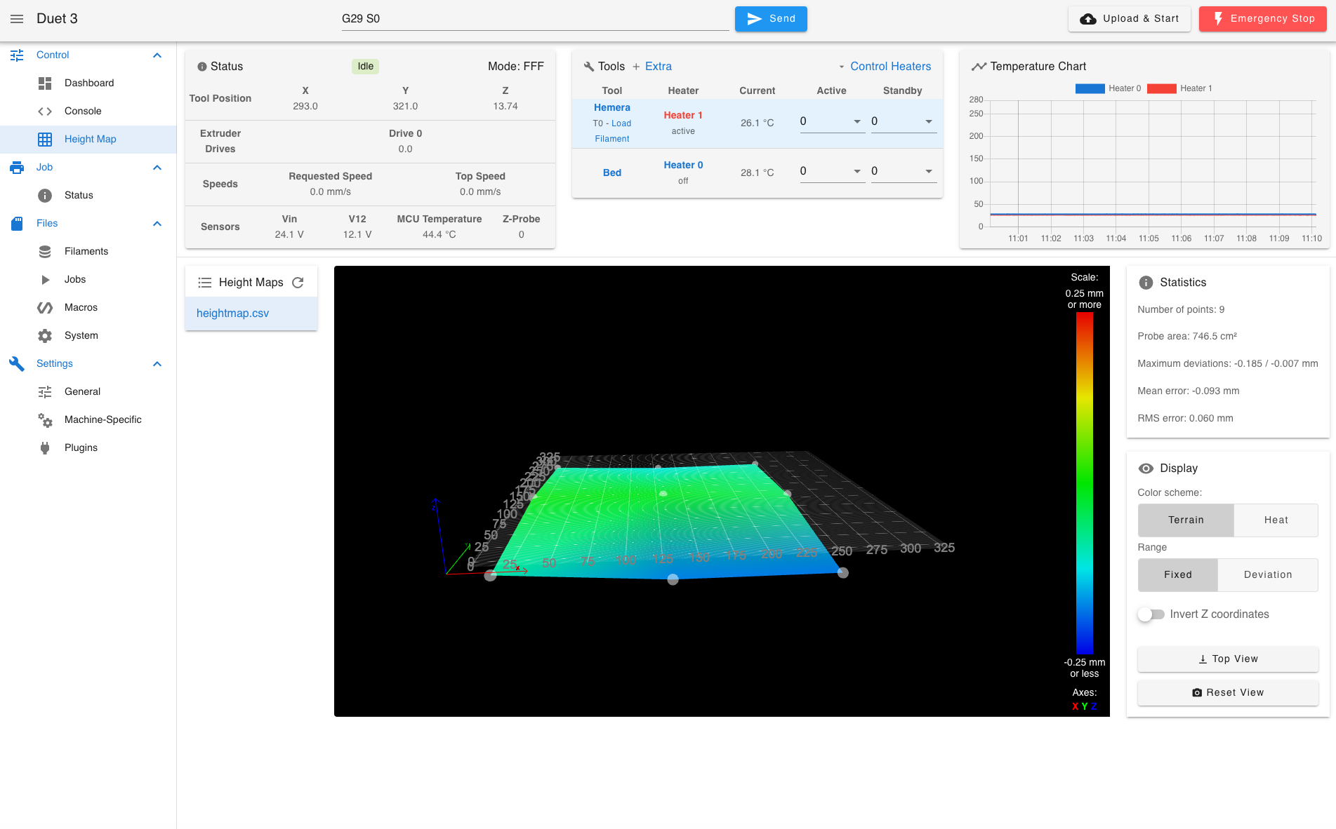
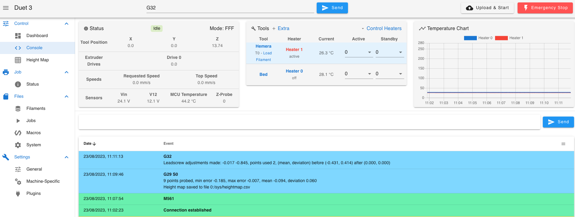
Now I run G32;

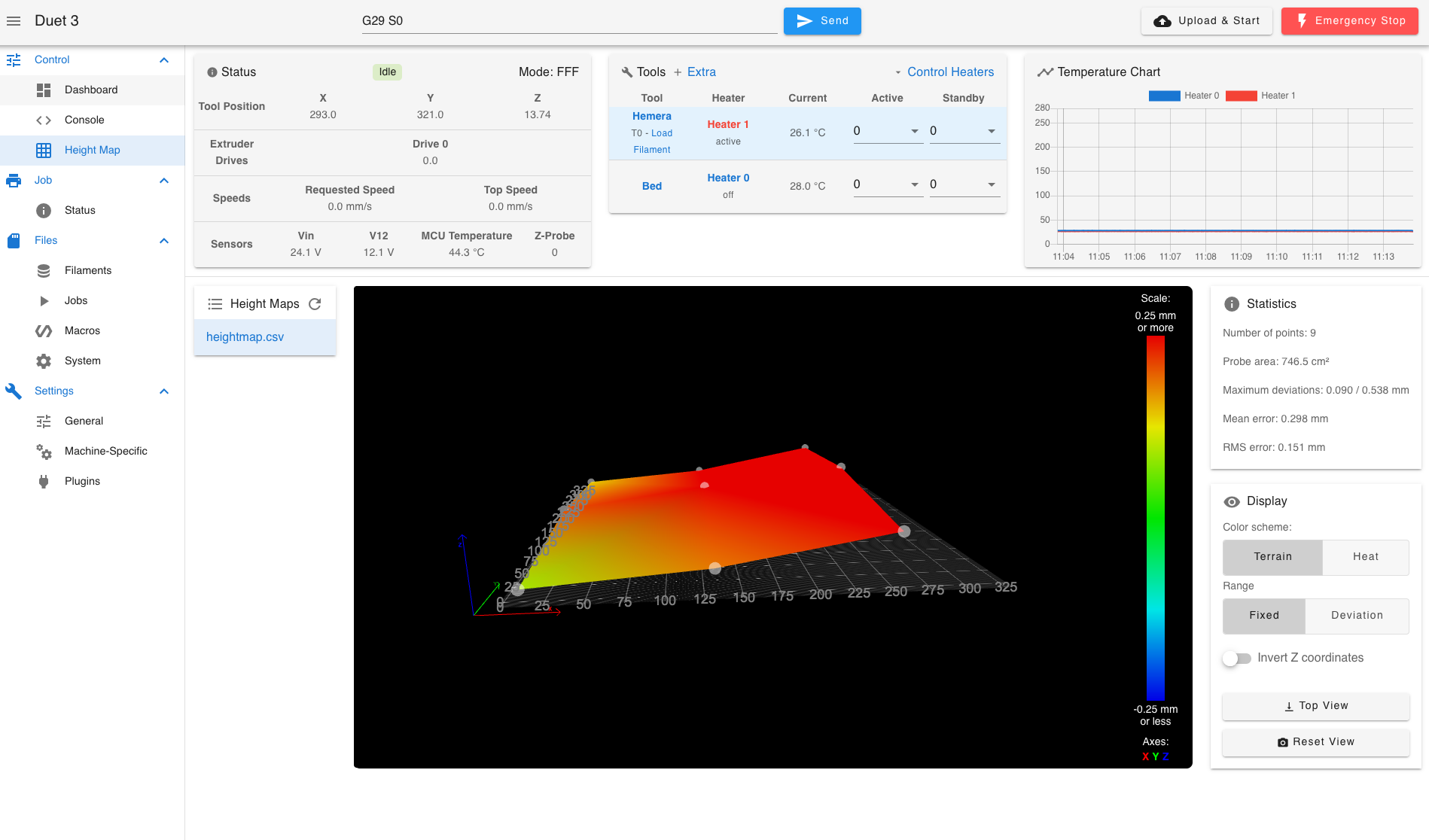
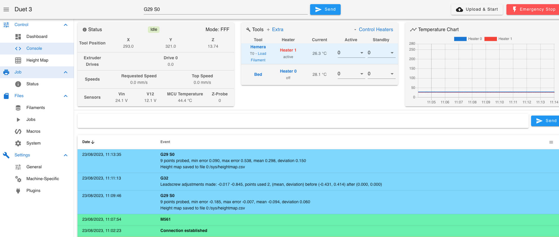
Run another scan of the bed. It raises the Right hand side up;


The more I repeat the worse it gets.
Is this because the Duet thinks it is close to the leadscrew, when its actually 165mm away?
I'm in the process (still), of building my 8mm cast tool plate bed, which will have 3 point levelling and the leadscrews will be closer to the bed, but I'll still have the issue on the right hand side.Is there away to resolve this?
-
@Dizzwold said in G31 P Parameter:
If I opted to use 2 Z-probes, 1 either side of the extruder, how would this work?
I don't think anyone has done that before. There is no functionality in the firmware to automate that. You can use different probes, but they would usually be for different tools. In your case, you could create two heightmaps and then combine them manually, but you would need to ensure your trigger height was identical, or manually correct for the variance.
Is your bed surface so bad that extrapolation of the edge isn't enough?
@Dizzwold said in G31 P Parameter:
Just to clarify the P value.
Yes, basically.
-
@Dizzwold said in G31 P Parameter:
Is this because the Duet thinks it is close to the leadscrew, when its actually 165mm away?
For leveling you should have the actual lead screw positions in the config. If it's going to wrong direction is sounds like you may have the order of the motors listed backwards.
https://docs.duet3d.com/en/User_manual/Connecting_hardware/Z_probe_auto_levelling
-
Thank you again.
@Phaedrux said in G31 P Parameter:
For leveling you should have the actual lead screw positions in the config
I was previously advised on the forum when I was setting the system up that I had to use coordinates within the print area dimensions?
@Phaedrux said in G31 P Parameter:
If it's going to wrong direction is sounds like you may have the order of the motors listed backwards.
Motor wiring is in the correct order. Drive 2 is the left Z axis motor, drive 3 is the right. When I run G32 it probes the centre of the bed then runs to the left leadscrew. That's correct?
I'll try to get the correct 'exact' coordinates for the leadscrews and see if this is the cause.
For ages I've been skipping G32 because of this and just using 2 engineering V blocks to set the bed's frame from the top Y axis rails.
Config.g
; Configuration file for Duet 3 MB 6HC (firmware version 3.3)
; executed by the firmware on start-up
;
; generated by RepRapFirmware Configuration Tool v3.3.13 on Mon Sep 19 2022 16:04:20 GMT+0100 (British Summer Time)

; General preferences
M575 P1 S1 B57600                                  ; enable support for PanelDue
G90                                                ; send absolute coordinates...
M83                                                ; ...but relative extruder moves
M550 P"Duet 3"                                     ; set printer name
M669 K1                                            ; select CoreXY mode

; Network
M552 P192.168.0.72 S1								;ip address
M554 P192.168.0.1									;gateway
M553 P255.255.255.0									;subnet mask

; Bed Leadscrew Positions
M671 X5:278 Y175:175 P2.0						; middle left, middle right

;xxxxx

G4 S1												;wait for expansion boards to start

; Drives
M569 P0.0 S0                                       ; physical drive 0.0 goes backwards
M569 P0.1 S0                                       ; physical drive 0.1 goes backwards
M569 P0.2 S1                                       ; physical drive 0.2 goes forwards
M569 P0.3 S1
;M569 P0.4 S1
M569 P121.0 S0                                       ; physical drive 0.3 goes forwards
M584 X0.0 Y0.1 Z0.2:0.3 E121.0                           ; set drive mapping
;M584 X0.0 Y0.1 Z0.2:0.3:0.4 E121.0
M350 X16 Y16 Z16 E16 I1                            ; configure microstepping with interpolation
M92 X80.00 Y80.00 Z400.00 E330.12; set steps per mm
M566 X900.00 Y900.00 Z60.00 E120.00                ; set maximum instantaneous speed changes (mm/min)
M203 X6000.00 Y6000.00 Z180.00 E1200.00            ; set maximum speeds (mm/min)
M201 X500.00 Y500.00 Z20.00 E250.00                ; set accelerations (mm/s^2)
M906 X900 Y900 Z900 E800 I30                       ; set motor currents (mA) and motor idle factor in per cent
M84 S30                                            ; Set idle timeout

; Axis Limits
M208 X-2 Y-8 Z0 S1                                 ; set axis minima
M208 X330 Y330 Z400 S0                             ; set axis maxima

; Endstops
M574 X1 S1 P"!121.io1.in"                              ; configure switch-type (e.g. microswitch) endstop for low end on X via pin !io1.in
M574 Y1 S1 P"!io2.in"                              ; configure switch-type (e.g. microswitch) endstop for low end on Y via pin !io2.in


; Z-Probe
;M574 Z1 Z1 S2									   ; set endstops controlled be probe
;M558 P8 C"^!121.io0.in" H5 F120 T6000                 ; set Z probe type to switch and the dive height + speeds
;G31 P500 X-46 Y-19 Z1.51 							; set Z probe trigger value, offset and trigger height
;M557 X19:244 Y-2:304 P12							; define mesh grid

; Z-Probe
M950 S0 C"121.io0.out"                             ; create servo pin 0 for BLTouch on tool board
M558 P9 C"121.io0.in" H10 F120 T6000                ; set Z probe type to bltouch and the dive height + speeds on tool board
G31 P25 X-39 Y-17 Z3.74                            ; set Z probe trigger value, offset and trigger height
M671 X5:278 Y175:175 P2.0 S5                       ; define positions of Z leadscrews, 5mm maximum correction
M557 X10:254 Y-2:304 P3                           ; define 12x12 mesh grid;


; Heaters
M308 S0 P"temp0" Y"thermistor" T100000 B4138       ; configure sensor 0 as thermistor on pin temp0
M950 H0 C"out0" T0                                 ; create bed heater output on out0 and map it to sensor 0
M307 H0 R0.187 K0.192:0.000 D1.89 E1.35 S1.00 B0   ; disable bang-bang mode for the bed heater and set PWM limit
M140 H0                                            ; map heated bed to heater 0
M143 H0 S120                                       ; set temperature limit for heater 0 to 120C
M308 S1 P"121.temp0" Y"thermistor" T100000 B4138       ; configure sensor 1 as thermistor on pin temp1
M950 H1 C"121.out0" T1                                 ; create nozzle heater output on out1 and map it to sensor 1
M307 H1 R2.498 K0.275:0.349 D6.79 E1.35 S1.00 B0 V24.0  ; disable bang-bang mode for heater  and set PWM limit
M143 H1 S280                                       ; set temperature limit for heater 1 to 280C

; Fans
M950 F0 C"121.out2" Q500                               ; create fan 0 on pin out4 and set its frequency
M106 P0 C"Part Cooler" S0 H-1                     ; set fan 0 name and value. Thermostatic control is turned off
M950 F1 C"121.out1" Q500                               ; create fan 1 on pin out5 and set its frequency
M106 P1 C"Extruder Cooling" S1 H1 T45              ; set fan 1 name and value. Thermostatic control is turned on

; Tools
M563 P0 S"Hemera" D0 H1 F0                         ; define tool 0
G10 P0 X0 Y0 Z0                                    ; set tool 0 axis offsets
G10 P0 R0 S0                                       ; set initial tool 0 active and standby temperatures to 0C

; Custom settings are not defined
; Emergency Stop
M950 J1 C"!io4.in"
M581 P1 T0 S0 R0
M582 T0


; Miscellaneous
M911 S10 R11 P"M913 X0 Y0 G91 M83 G1 Z3 E-5 F1000" ; set voltage thresholds and actions to run on power loss

T0

M501
Bed.g
; bed.g
; called to perform automatic bed compensation via G32
;
; generated by RepRapFirmware Configuration Tool v3.3.13 on Mon Sep 19 2022 16:04:20 GMT+0100 (British Summer Time)
;M561 ; clear any bed transform
;G29  ; probe the bed and enable compensation


M561
M671  X5:278 Y175:175 P2.0
G28			; home
G30 P0 X5 Y175 Z-9999				; probe center left
G30 P1 X278 Y175 Z-9999	S2			; probe center right
G1  X0 Y0 F12000
Dizzwold
-
Changing the leadscrew positions to their exact positions seems to have fix this issue.
Another problem I'm experiencing is if I use M401 to deploy the BL Touch Z-probe, M402 will not retract it or M280 P0 S90. If I try to home Z or anything I get the following error;
Error: Probe already triggered at start of probing moveI've tried to do M98 P"config.g", but I lose connection. I've not updated yet from this thread where a bug was found;
https://forum.duet3d.com/topic/33139/further-connection-issues?_=1692864007271Dizzwold
-
@Dizzwold said in G31 P Parameter:
I was previously advised on the forum when I was setting the system up that I had to use coordinates within the print area dimensions?
You must probe a spot physically reachable by the probe, but the position of the lead screws themselves should be accurate within ~10mm in absolute coordinates. So if they are off the bed area, use the actual position relative to the origin point.
@Dizzwold said in G31 P Parameter:
M671 X5:278 Y175:175 P2.0
Pnnn Pitch of the bed levelling screws (not used when bed levelling using multiple independently-driven Z motors). Defaults to 0.5mm which is correct for M3 bed levelling screws.
Are you sure your pitch is correct?
-
@Dizzwold said in G31 P Parameter:
M402 will not retract it or M280 P0 S90.
Please upload your deployprobe.g and retractprobe.g files.
-
Thank you once again.
This is where it gets a bit silly and one of the reasons for building my own cast tool plate/build plate.
The Tronxy X5SA Pro 330 x 330mm build plate I'm currently using has 2 independant Z Axis motors, left and right centre of the build plate.
It then has 6 bed adjustment screws 3 running along the front and 3 along the back, which fasten and adjust the bed from the bed frame.
The 2 leadscrews are 2mm pitch (confirmed by Tronxy) and the 6 adjustment screws are M3 at I guess 0.5mm pitch.So its quite a painful experience after I've tinkered with things and have readjust the bed to get it within a reasonable tolerance.
1, I have to level the bed frame to the Y Axis top rails
2, Run a 3x 3 mesh bed probe, roughly where the 3 front and 3 back bed screws are (and along the centre line)
3, Adjust the screws
Repeat 2 & 3 many times (after tinkering or not used for a while)
Run a 12 x 12 mesh bed probeOnce the above is done, and if I'm using the printer the next day for example, I do number 1 with the engineering blocks, then run my Bed Adjustment Screws Macro (which just probes the bed centre and 4 corners), then set the Z offset (this was with the Tronxy inductive Z Probe).
I've not printed yet using the BL Touch.So yes it's organised chaos.
Bed Adjustment Screws.g
M561
G28
M671  X5:278:278:5 Y5:5:302:302 P0.5
G30  P0 X5 Y5 Z-9999				; probe front left
G30  P1 X278 Y5 Z-9999			; probe front right
G30  P2 X278 Y302 Z-9999			; probe rear right
G30  P3 X5 Y302 Z-9999 S4  		 ;probe rear left
G1   X0 Y0 F12000
deployprobe.g
M280 P0 S10
retractprobe.g
M280 P0 S90I also hadn't answered your previous question. On power-up Yes the Z-probe does a deployment and retraction test twice.

-
I've just updated to 3.4.6.
M401andM402now work as they should.When I type
M98 P"config.g"I still get the following response and have to manually press stop on the paneldue;
Connection lost, attempting to reconnect...Maybe this is a bug similar to the following thread;
https://forum.duet3d.com/topic/33139/further-connection-issues?_=1692864007271Dizzwold