New heated enclosure printer
-
@mrehorstdmd and @Phaedrux Thanks for the suggestions. I am using Cura 5 with the variable line widths but most of the walls on this part are only 2 passes wide so that only has an effect in certain areas. My relatively tall and slender beads were likely having an easy time tipping over a little.
I'll try a 1.2mm width and .6mm hight and see what the results are.
Any other setting tips? Cura's got a ton of settings and I'm not sure which to pay attention to. -
Cura has a LOT of settings. If you're serious about mastering it I suggest unhidding all of the settings and add the "settings guide" tool tip plugin that shows details on what each setting does with illustrations in a tool tip popup when you hover over the setting. Cura has an online settings guide as well that is useful, though not entirely complete.
-
@phaedrux said in New heated enclosure printer:
Cura has a LOT of settings.
That's an understatement! I've been doing that and adjusting as seemed reasonable, but what is resonable is always a good question!
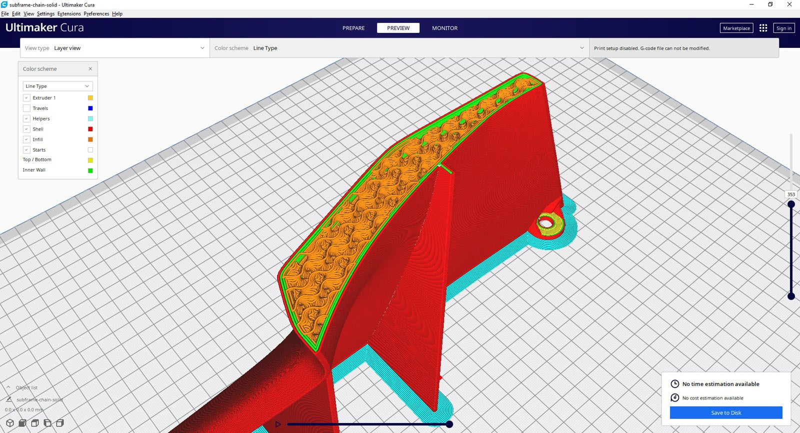
I've found some settings that would eliminate a lot of the small interior extrusion moves, but am having a problem in that what I thought were shrinkage remnants from the ribs is actually part of the toolpath Cura is generating. Cura is making small moves on the surface opposite the ribs even though the STL mesh is for a smooth surface. They are clearly displaying on the G-code preview in Cura and in the printed part.
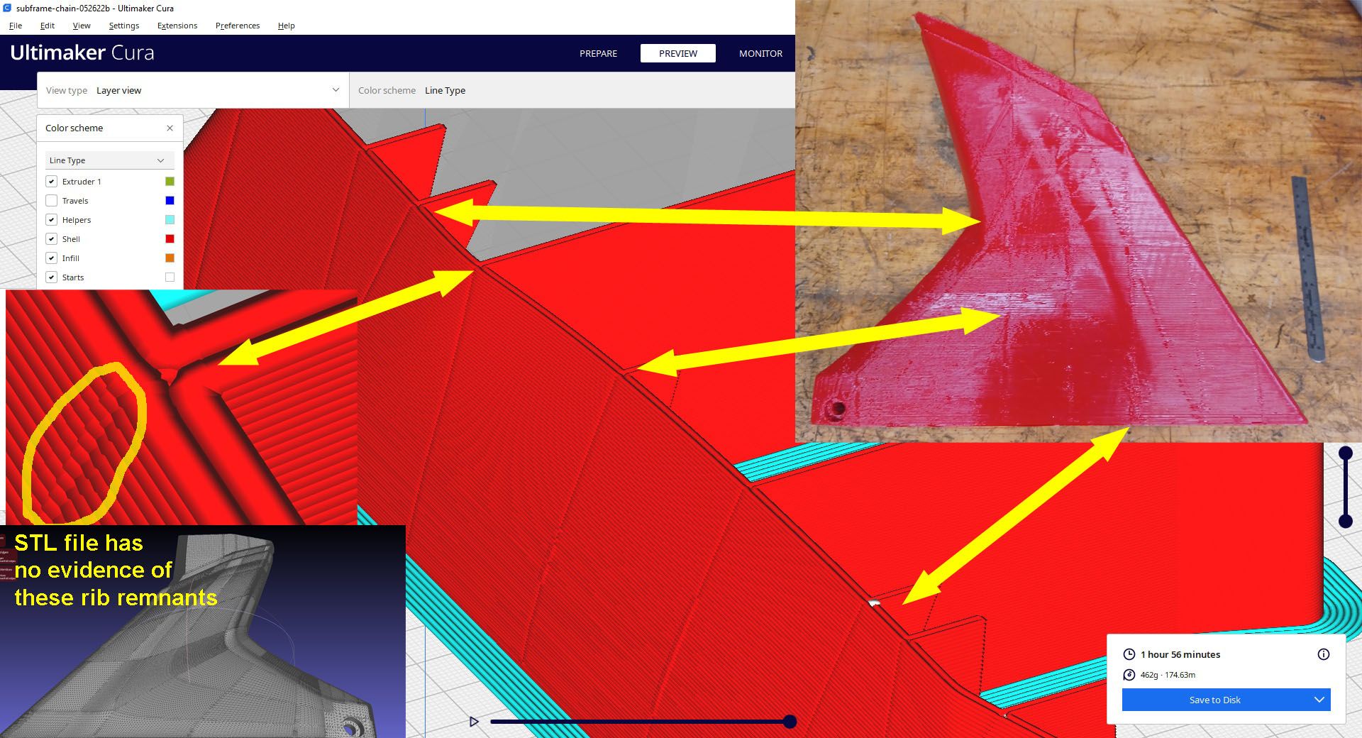
I'm not sure how to tell Cura not to do this.
-
0.7x0.3 Volcano PLA.curaprofile.txt
I don't think I've ever seen it do that before, but I don't think I've ever printed so many fin like structures either.
Here's a profile I quickly tuned up from scratch when I installed Cura 5.
-
@phaedrux Thanks for the Cura profile, its nice to start with something besides a clean sheet!
Had a frustrating few days, starting with the bed heater temp sensor going bad. At first I was not sure as no errors were thrown, but then I was getting heater faults and saw obvious spikes on the graph. To get printing again I mounted a PT1000 sensor embedded into the aluminum bed and now it seems it be working. Reran the M303 cycle on the bed with no warnings or errors. Also had a couple of mechanical gremlins that had to be fixed. Also did some print temp tests and reduced the nozzle temp from 250 to 235C.
So, after this tweaking I was able to finally get another part to finish printing. Results are somewhat mixed, but at least it finished! I am a little frustrated as the results are still worse than the first part off the machine!

First part off the machine:

I added a couple of ribs to add stability to the part as it is being printed. There were a bunch of visible remnants on the front face, but these seemed correlated pretty well with the Cura toolpaths. In the preview there was either a start point or some change in extrusion in the problem areas. So hopefully these areas are setting related and not printer related and can be eliminated through software tweaking.
The other issue concerns thermal performance. The ends of the part and ribs seemed to be falling off the previous layer.
 This has been happening since the first print.
I think most of the problem is the overall thermal management. I noticed that with the nozzle set at 230C, the bed set at 90C, and the chamber set at 60C, once it has been printing for about 5 min the bed sensor reads 94C and the SSR that controls it never goes on. If I reduce the chamber temp to 55C, the bed temp lowers to 92C. These temps are pretty stable within +/-1.0C over time. I was very surprised at how hot the chamber heater can keep the bed, so it seems that the temps are rising uncontrollably as the part builds. On a few layers I held a small air gun at the print nozzle and manually cooled the extrusion and the bead seemed to behave better at those direction changes. I think one addition should be a layer cooling fan that turns on after 50 or so layers.
Also thinking about a smaller nozzle so that each wall is 3 passes instead of 2. Having the center bead laid down on middle of the previous layer would reduce the ability of the outer pass to sag out of position. Maybe.
Thoughts? Suggestions?
-
Maybe not a bad time to give another slicer a try. Prusa Slicer for instance. Cura does not seem to handle your style of part very well.
-
@phaedrux Yes, I'm printing a box now that is coming out very consistently, so think that the slicer is the issue. I can try Prusa but first am asking someone on the Ultimaker forum that made a Cura build branch to help slice thin wall parts if they are willing to help out a bit.
-
OK, just printed a 150x150x75mm block with 20% infill and it came out quite nice. If I can get the fairings to look anywhere near this good it will be a success.

The top surface fill was a little rough where it met the walls but otherwise was good. The middle section was me trying lower print temps, the good parts were 230 to 220, the non print is 210, then back up to 220.

I got some feedback on the Ultimaker forum to go back to 4.13 since the change to variable line widths in 5.0 was a major change with lots of new settings and the effects of them all are not well known. The gcode preview in Cura 4.13 had much cleaner toolpaths with none of the weird artifacts from 5.0. So I am printing a part one out now with a 4.13 sliced file and tomorrow will fit a layer cooling fan and hope that seals the deal.
-
OK, making some progress! This part is done with Cura 4.13 and no variable print widths and the toolpaths looked better in the preview and the parts looks a lot better.

Except for those weird problems at the ends of the ribs.

Some places it prints perfectly, some places, not.

This is frustrating, sections of the print are perfect so that means that a lot of things need to be working correctly, and sections are crappy so means that something is amiss. I have a 0.8mm nozzle sliced part printing now with 4 printhead passes per layer. So far, so good, but it is only 75mm into the print.
As an aside, I am realizing the speed limitations are mostly the extruder, not the XY motors. With the smaller nozzle and layer thickness the print speed is a lot faster, so even with 2x the layers, it is only a 4 hr part as opposed to the 3 hr with the 1mm nozzle. Printing is now at 100mm/sec actual and rapids at 750mm/sec. Maybe once it is printing consistently I'll get a bigger motor for the extruder and see how fast it can push filament through.
For extruder calibration, is the 'mark and measure' or the 'extrude and weigh' a more accurate approach? Or another technique?
-
@coseng said in New heated enclosure printer:
For extruder calibration, is the 'mark and measure' or the 'extrude and weigh' a more accurate approach? Or another technique?
I think you're talking two separate things here.
Mark and measure would be for getting the steps per mm accurate so it's moving the correct amount of filament based on the motor and gearing anyway.
The extrude and weigh approach is more for testing the limits of flow, which is going to take melt rate, back pressure, slippage, etc into account.
Set the steps per mm at a low speed, and then set your flow rate for actual printing.
This is a pretty basic guide on establishing both and should let you find the limits of flow rate ballpark at least. https://duet3d.dozuki.com/Guide/Ender+3+Pro+and+Duet+Maestro+Guide+Part+4:+Calibration/40?lang=en#s165
-
@phaedrux I think you're talking two separate things here.
I meant comparing the weight of the extrusion of a 100mm feed command and 100mm of filament. Seems like either method could work. I'm going to focus on getting those print problems resolved before trying to go faster.
Do you think the print problems at the rib ends could be helped by using the pressure advance functionality? Maybe there is slightly too much material being extruded at these direction reversals, causing them to bunch up and fall over.
-
@coseng said in New heated enclosure printer:
Seems like either method could work.
Yes I see what you're saying now. I haven't compared the results of using either technique. It would be interesting to see how much the steps per mm would differ.
Yes if you aren't using pressure advance yet it would be a good idea to start. I don't know if it would solve the rib problem. It almost looks like dribble on a retraction move, or like Cura is still doing something stupid. It would help to see it in action while printing to see what is actually happening there.
The other thought about the ribs I had, is that you've designed them as if for an injection molded part. Perhaps rather than a thin rib, you could create a triangular profile instead.
-
It almost looks like dribble on a retraction move, or like Cura is still doing something stupid.
There are no retractions in those areas and the g code preview shows a clean toolpath with no weirdness, so I am thinking maybe overextrusion is causing there to be too many people in the bed and one falls off the edge. Up close, the extrusiuon bead is complete and consistent, just not in the proper place.
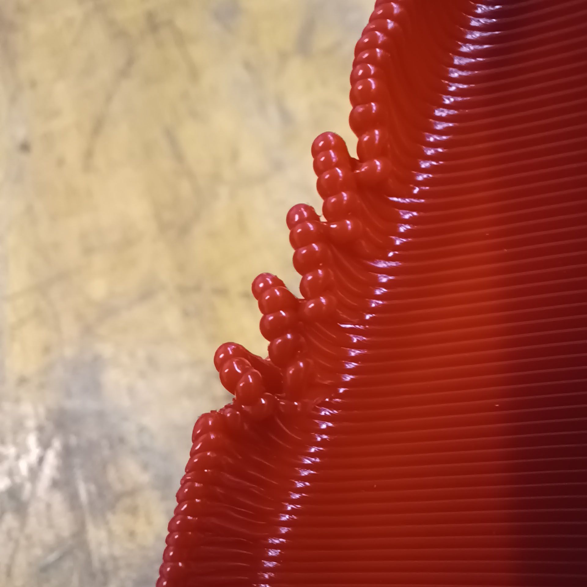
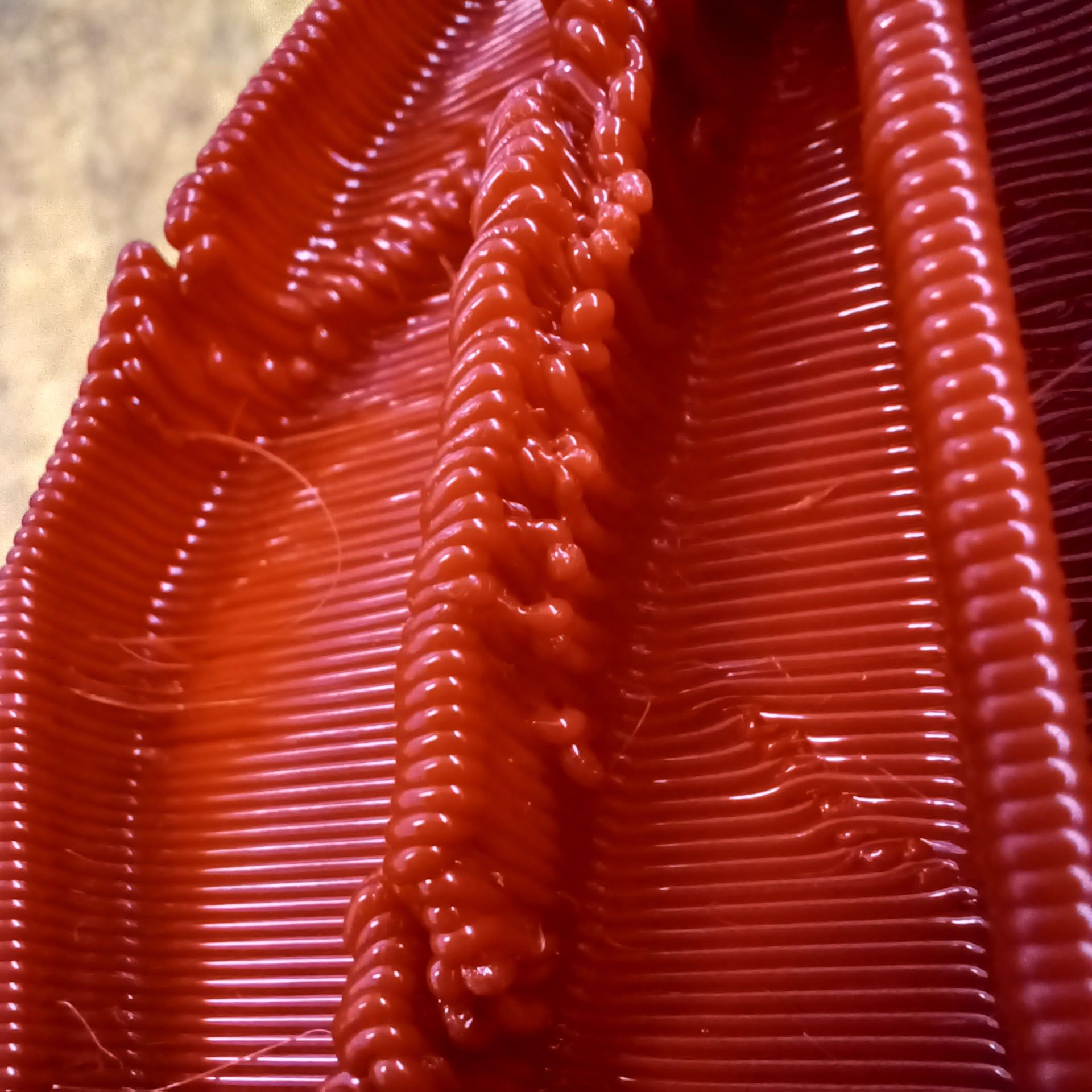
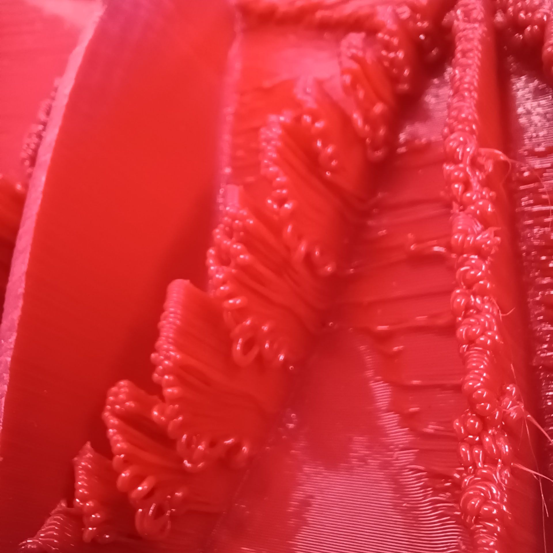
I turned pressure advance on with a console command halfway through this 0.8mm nozzle print and let's see if it makes a difference. The print speeds became a lot more variable so I also increased the extruder jerk value to 480, at which point it did not seem that much slower.
-
@phaedrux said in New heated enclosure printer:
The other thought about the ribs I had, is that you've designed them as if for an injection molded part. Perhaps rather than a thin rib, you could create a triangular profile instead.
Yes, that is one option but some of the ends of the part have similar geometry so would be hard to do there. I can try that on the rib ends where it is possible to reduce the possible places where it can happen.
-
OK, making some progress. This is the first 0.8mm nozzle part off the machine. 4hr3min print time, 0.4mm layer height. About halfway though the print I activated pressure advance with a 'M572 D0 S0.10' command.

The change did not eliminate the rib end wiggles, and in fact one wiggle that was already happening continued to happen.

There was a visible difference in the accuracy of the toolpaths, with the no-PA areas showing a better finish and more accurate toolpath than the areas with PA.


The two tall ribs with the triangular ends was where the accuracy difference was most apparent. It seems that the PA was causing a decent variation in the extruded line width. The no-PA areas were triangular and straight while the lines in the areas with PA were not straight and had some convexity to them. Looking at the top layer it seems that the lines were thinning at each end. Maybe the S0.1 was too much PA?I'm starting to wonder if the inertia of the extruded bead is causing it to flop over when the printhead changes directions quickly. Or something dynamical like that, since the gcode is clean and there do not seem to be obvious mechanical problems.
I think the next test is to add a layer fan to see if cooling them quicker will prevent the problems. Though I do have second thoughts about that approach, since looking at the close-ups in the previous post it seems that there is just too much material being printed for the layers to stack on each other cleanly. They seem to be all jumbled together with no room for proper placement. But on the areas without such an abrupt direction reversal the layers are stacking very cleanly, so is it only on those areas with an abrupt change in direction. Weird.
-
You'll need to tune the amount of pressure advance used. It's not as simple as turn it on and go.
https://docs.duet3d.com/en/User_manual/Tuning/Pressure_advance
Adding a layer fan would be a good idea. The ends look like they are just squirting out into thin air and once it starts, the layer that comes above it has nowhere to attach to, so it just spirals upward.
-
@phaedrux I think that activating pressure advance did not make an improvement to the main problem at hand, so in the interest of not trying to tweak too many variables at once, will turn it off and try a layer fan first. If the fan does not do it, both can be done and then will have a full data set for comparison.
-
Last night I made some modifications to the part to see how much of the thin wall nature is the issue. I thickened the part to about 20mm and sliced it with a 0.8mm nozzle, 0.4mm layer, 20% gyroid infill and 2 walls. The result was the best yet, with a 5hr3min print time.

I'm really happy with the surface finish and if this last issue can be resolved will consider the printer a complete success.

Though the same problem happened along one of the inner edges.

The narrow ribs with no triangular ends (done to try to make the problem happen) printed great, through they did show signs that pressure advance could be beneficial. Most of the wall was 2.8mm thick, but it fattened up to a teardrop shaped 3.5mm bulge at the end.

Now to install the layer fan and duct and run the same file again, modified to turn the fan on after 100 layers.

-
@coseng said in New heated enclosure printer:

Could you upload the gcode for this print? Would like to take a peek and see whats going on there.
-
@sebkritikel Here's a screenshot of the area. The problem area is the sharp vertex in the forground. The gcode is 28MB, where would I upload it to here?
