slowing down a non-powered stepper motor
-
@fma said in slowing down a non-powered stepper motor:
BTW, guys, how do you connect the belt to the Z carriage (bed)? Do you use an open belt, or a closed one?
Hi,
I don't understand your question. Can you elaborate?
Thanks.
Frederick
-
When using a belt to lift the bed, is it better to use an open one, or a loop? And how to you clamp it to the bed?
And is a width of 6mm enough, or should I go for 9mm?
-
@fma said in slowing down a non-powered stepper motor:
When using a belt to lift the bed, is it better to use an open one, or a loop?
I cannot visualize how it would be done without using a loop of some sort.
And how to you clamp it to the bed?
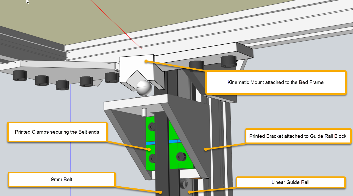
Well on my printers it is done like this. Hope this is enough detail. If not ask for more.

And is a width of 6mm enough, or should I go for 9mm?
I played it safe and used 9mm.
Frederick
-
Thanks for the picture! I had the motor turned 90°, which is not as good as your solution!
About the belt: it belt can be one big closed loop, or a cut part. I have the feeling that a closed loop will be more robust, and less prone to break...
-
I use 2x 9 mm glass core belts to lift the 3.5 kg bed assembly in my printer.
I measured belt stretch using both steel core and glass core belts. The glass core belts (Gates LL2MR09) stretch about 3x the steel core belts, but for the stuff I print, it doesn't matter.See: https://drmrehorst.blogspot.com/2018/12/comparing-steel-core-and-glass-core.html
I had an interesting failure in a belt clamp when I was using steel core belts: https://drmrehorst.blogspot.com/2018/12/another-interesting-3d-printer-failure.html Don't do what I did!
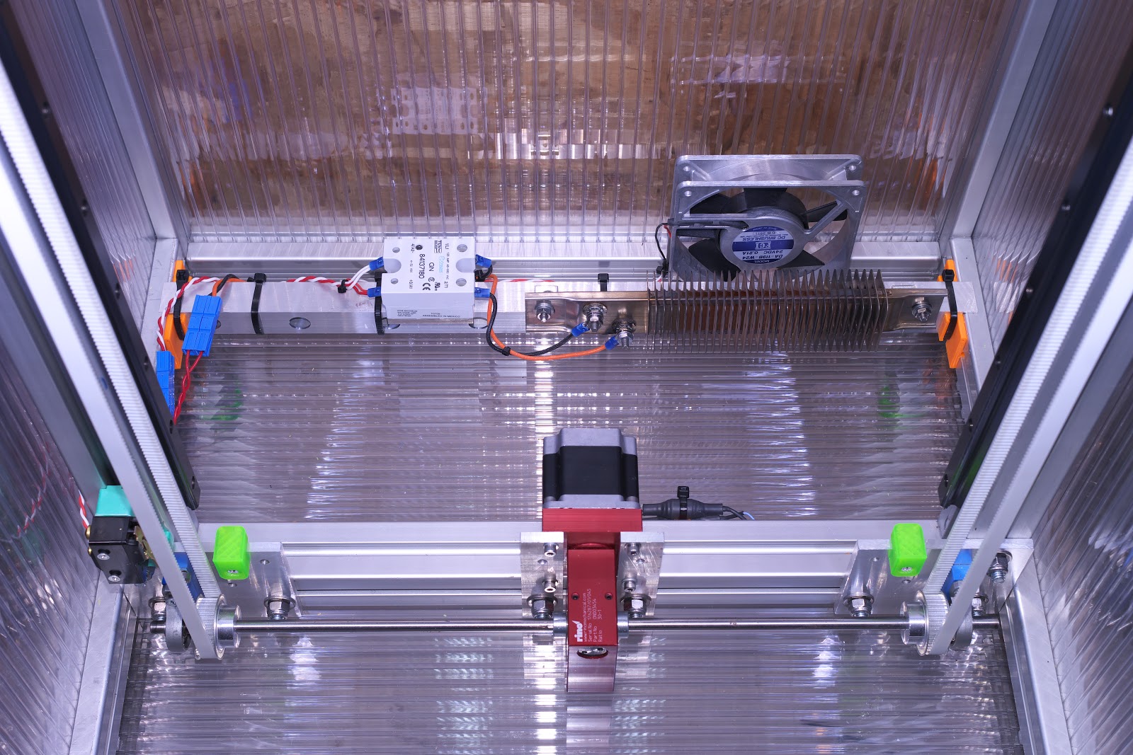
This is the business end of the Z axis- I uses a 30:1 worm gear reducer to turn a shaft with two 60 tooth pulleys that lift the bed assembly.

The photo was taken when I was still using steel core belts (before the clamp failure) which have since been swapped for glass core GT2 belts. At the top of the Z axis there are just two pulleys made from stacked F608 skate bearings (which I also used in the XY stage). -
@fma said in slowing down a non-powered stepper motor:
Thanks for the picture! I had the motor turned 90°, which is not as good as your solution!
About the belt: it belt can be one big closed loop, or a cut part. I have the feeling that a closed loop will be more robust, and less prone to break...
The belt looks like a loop since the cut ends are clamped under those green pieces in the drawing which have ridges on the surface you cannot see which match the belt.
The idler pulley at the top, which you cannot see in the image, is adjustable to set belt tension.
Frederick
-
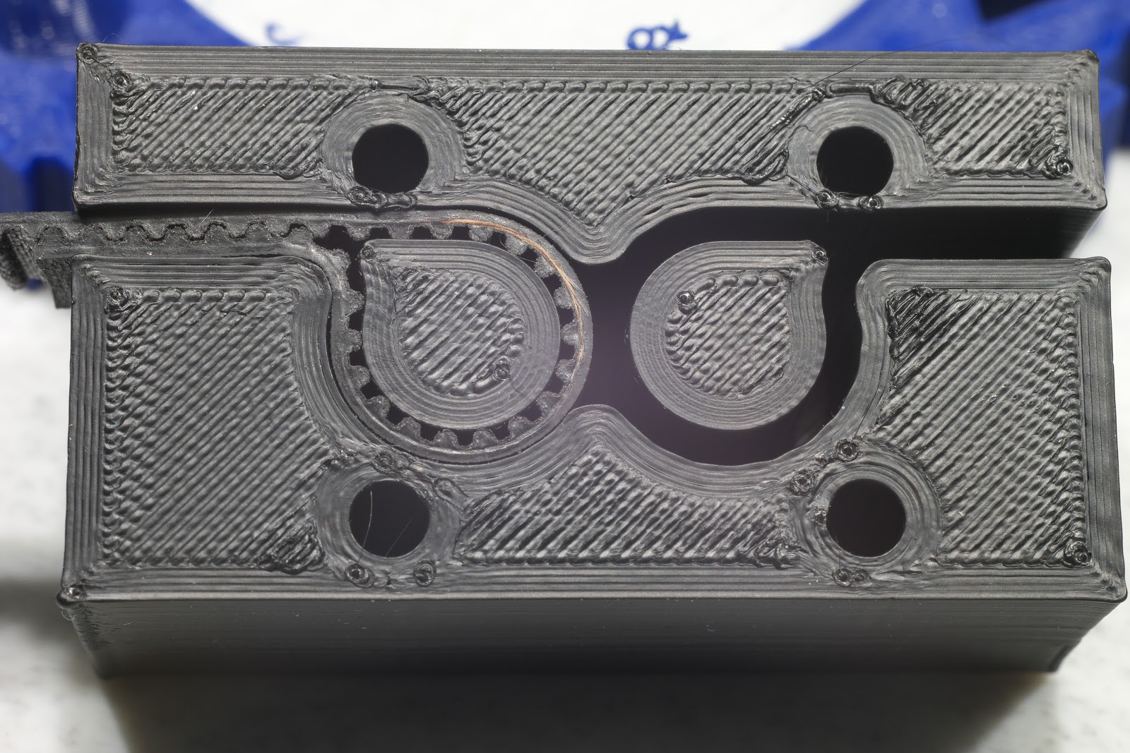
@fma I used open belt formed into a loop by clamping the ends in printed clamps that mount on the Z axis bearing blocks. No closed loop belt is needed. I initially used a simple slot type clamp that failed with steel core belt so I switched to a clamp similar to one I printed and is still working after about 6 or 7 years. You simply fold the belt back on itself and feed the folded part through a slot that keeps the teeth interdigitated. Like this:

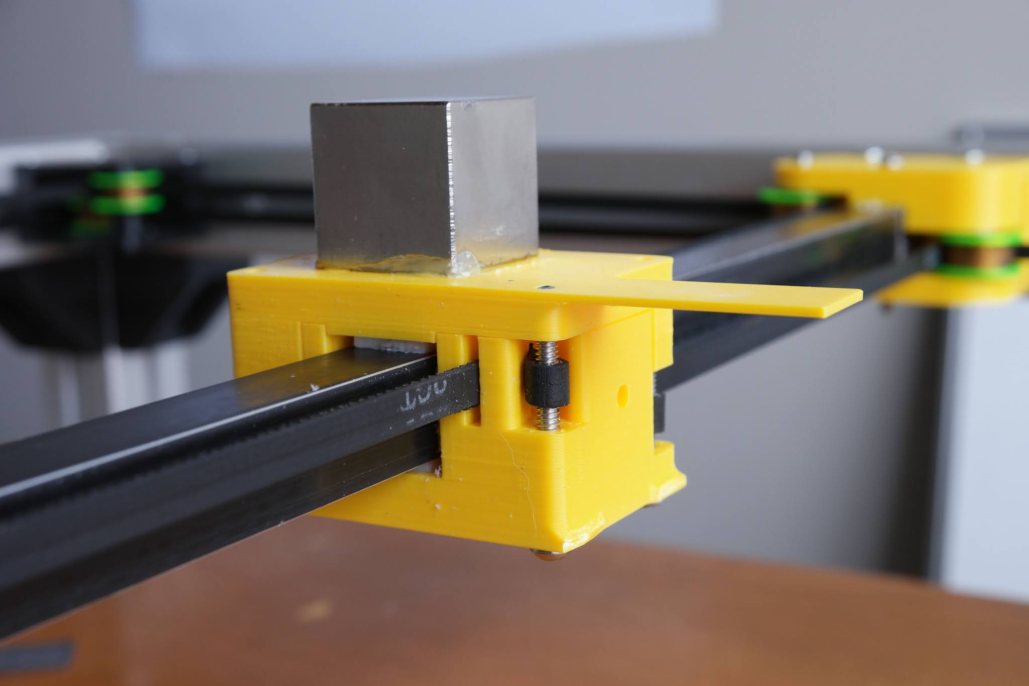
The center of the loop in the clamp can be printed (as I did) or it can be the screws that hold the clamp to the bearing block (as was done here) or to a bracket that attaches to the bearing block:

-
Thank you very much for your answers!
-
@fma could also drive you z belt with a worm gearbox. Worm gears can't be back driven.
-
@breed yes, that's mrehorstdmd's solution.