Nema 23 Backlash on direction change
-
Hi there,
I am using two Nema23 motors for one driven axis and I have some sort of backlash when changing the direction.
I’ve triple checked the mechanics and even changed a lot of parts to no avail. After a lot of testing, it seems that the motor/motor controller is the problem. The board and the firmware are probably not the cause of the error as I’ve flashed Marlin on another board (SKR 1.4 Turbo) and the error was the same as with RRF and the SKR Pro 1.2 board in SBC mode. Mechanical problems are also less likely because the problem is right at the motor side.The problem occurs when changing directions. I have to drive the motor via software about 48 steps (80steps/mm on selected axis with 64 microstepping and interpolation (Marlin setup), rotated through software 0.6mm --> 80*0,6=48steps/mm) where the motor doesn’t turn. Right at the next time I hit 0.1mm movement the motor begins to turn.
This only happens when the system is under tension. If I decouple the axis from the load the error is gone. I did a rough calculation on how big the forces are to overcome the friction and it was about 2Nm. I drive the axis with 2xNema23 with each 1,9Nm directly coupled to the axis (to isolate other possible errors) which should be sufficient in theory.
I have tried upping the motor current from 2,8A up to 4A (for a short period of time) and different microstepping values to no avail.Could this be a driver problem (maybe timing)?
Here are my specs:
-
Board: SKR Pro 1.2 running in SBC mode
-
Firmware: RepRapFirmware for STM32F4 based Boards (biquskrpro_1.1) version 3.3.0_11 (2021-11-04 23:02:01) running on STM32F4 (SBC mode)
-
Driver: 2xTMC5160 for Nema23, rest is TMC2209
-
Settings in board.txt:
//TMC Smart Drivers
stepper.numSmartDrivers = 6;
//TMC5160 specific settings
stepper.num5160Drivers = 3;
stepper.spiChannel = 2;
//SPI in slot 0-2, UART in slot 3-7
stepper.TmcUartPins = {A.15, B.8, B.9, D.4, D.1, D.6, F.11, G.10, NoPin, NoPin, NoPin}
//Sensorless homing settings
stepper.TmcDiagPins = {NoPin, NoPin, NoPin, E.15, E.10, NoPin, NoPin, NoPin, NoPin, NoPin, NoPin} -
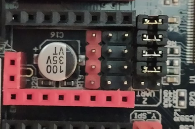
Jumper setup:

-
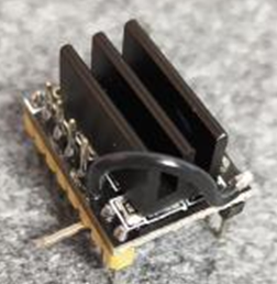
Driver modifications: Bend the CLK pin, connected CLK to GND as discussed in various forums:

-
Relevant info about driver setup:
M569 P0 S1 D3 V100 H30 ; Y1 physical drive 0 goes forwards M569 P2 S1 D3 V100 H30 ; Y2 physical drive 2 goes forwards M584 X4 Y0:2 Z3 E5 ; set drive mapping M350 X16 Z16 Y16 E16 I1 ; configure microstepping with interpolation M92 X81.34 Z81.34 Y25 E416 ; set steps per mm M566 X700.00 Z700.00 Y500 E1000 ; set maximum instantaneous speed changes (mm/min) M203 X15000.00 Z15000.00 Y1000 E20000 ; set maximum speeds (mm/min) M201 X1000.00 Z1000.00 Y500.00 E5000 ; set accelerations (mm/s^2) M906 X1000 Z1000 Y2800 E1000 I30 ; set motor currents (mA) and motor idle factor in percent M84 X Y E0 S3000 ; Set idle timeout- M122 Diagnostics:
m122 === Diagnostics === RepRapFirmware for STM32F4 based Boards (biquskrpro_1.1) version 3.3.0_11 (2021-11-04 23:02:01) running on STM32F4 (SBC mode) Used output buffers: 1 of 40 (10 max) === RTOS === Static ram: 18240 Dynamic ram: 63724 of which 40 recycled Never used RAM 48040, free system stack 179 words Tasks: SBC(ready,8.0%,338) HEAT(delaying,0.0%,316) Move(notifyWait,0.0%,333) TMC(delaying,3.5%,147) MAIN(running,84.7%,621) IDLE(ready,3.7%,30), total 100.0% Owned mutexes: HTTP(MAIN) === Platform === Last reset 00:00:16 ago, cause: [software] Last software reset at 2021-12-07 16:11, reason: User, none spinning, available RAM 48040, slot 1 Software reset code 0x0013 HFSR 0x00000000 CFSR 0x00000000 ICSR 0x00400000 BFAR 0xe000ed38 SP 0x00000000 Task SBC Freestk 0 n/a Error status: 0x00 Step timer max interval 0 MCU temperature: min 47.7, current 48.4, max 48.4 Supply voltage: min 24.0, current 24.0, max 24.0, under voltage events: 0, over voltage events: 0, power good: yes Heap OK, handles allocated/used 99/2, heap memory allocated/used/recyclable 2048/32/0, gc cycles 0 Driver 0: position 0, 5160 standstill, reads 15680, writes 17, SG min/max not available Driver 1: position 0, no-driver-detected Driver 2: position 0, 5160 standstill, reads 15680, writes 17, SG min/max not available Driver 3: position 0, 2209 standstill, reads 1702, writes 13, error r/w 0/1, ifcnt 27, timeout 0, SG min/max not available Driver 4: position 0, 2209 standstill, reads 1701, writes 13, error r/w 0/1, ifcnt 27, timeout 0, SG min/max not available Driver 5: position 0, 2209 standstill, reads 1701, writes 13, error r/w 0/1, ifcnt 27, timeout 0, SG min/max not available Driver 6: position 0 Driver 7: position 0 Driver 8: position 0 Driver 9: position 0 Driver 10: position 0 Date/time: 2021-12-07 16:12:09 Slowest loop: 1.19ms; fastest: 0.05ms === Move === DMs created 83, maxWait 0ms, bed compensation in use: none, comp offset 0.000 === DDARing === Scheduled moves 0, completed moves 0, hiccups 0, stepErrors 0, LaErrors 0, Underruns [0, 0, 0], CDDA state -1 === Heat === Bed heaters = 1, chamberHeaters = 2 Heater 0 is on, I-accum = 0.0 === GCodes === Segments left: 0 Movement lock held by null HTTP* is doing "M122" in state(s) 0 Telnet is idle in state(s) 0 File is idle in state(s) 0 USB is idle in state(s) 0 Aux is idle in state(s) 0 Trigger* is idle in state(s) 0 Queue is idle in state(s) 0 LCD is idle in state(s) 0 SBC is idle in state(s) 0 Daemon is idle in state(s) 0 Aux2 is idle in state(s) 0 Autopause is idle in state(s) 0 Code queue is empty. === SBC interface === State: 4, failed transfers: 0, checksum errors: 0 Last transfer: 2ms ago RX/TX seq numbers: 489/489 SPI underruns 0, overruns 0 CRC errors header 0, data 0 Disconnects: 0, timeouts: 0, IAP RAM available 0x0c644 Buffer RX/TX: 0/0-0 === Duet Control Server === Duet Control Server v3.3.0 Code buffer space: 4096 Configured SPI speed: 8000000Hz Full transfers per second: 33.85, max wait times: 13.0ms/0.0ms Codes per second: 3.65 Maximum length of RX/TX data transfers: 2565/904 -
-
@semi55 If the motors move fine when not loaded and not when under load then I would say you have some sort of mechanical issue. My guess is that the you are underestimating the force needed to overcome the friction when reversing motion. Remember that the rated torque will be for a full step and will likely be considerably less when using microstepping (this is especially true at low speeds like when you are reversing the drives). Can you post a picture of the mechanical setup you are using. 80steps/mm with a 64 microstepping sounds pretty low to me. I think I'd be considering some sort of mechanical solution (gearing of the drive system).
-
@gloomyandy The 80steps/mm are not actually calibrated to the real need of the setup as I am only testing the proper function right now.
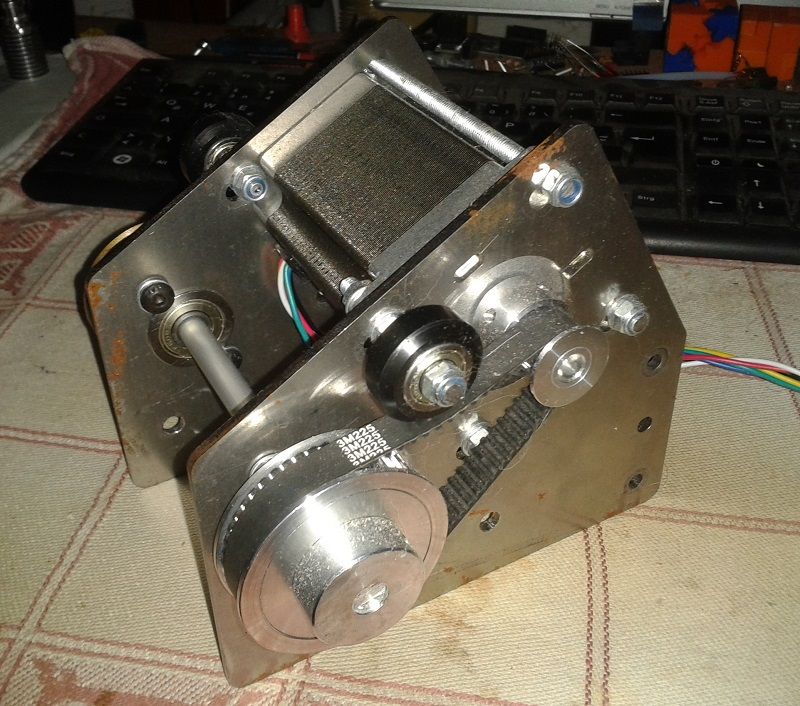
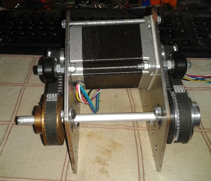
This is my setup

I've had a drive system with a belt and a gear ratio of 3:1 with 2x1,26Nm Nema23 motors which resulted in the same error. I then coupled 2xNema23 1,9Nm motors directly to the axle to isolate the mechanics (thought that maybe the belt stretches too much when changing directions).As you can see in the picture, I've added zip ties around each section where the error could occur to exaggerate the movement of each section (with sections I mean 1)Motor shaft, 2)Coupling, 3)Printer axle, 4)Printer pulley on axle) so I can spot if there would be any mechanical play (I've put some magnets on the shaft of the motor on the back with a zip tie).
If the power of the motors would be to weak, wouldn't they skip steps right away and not be able to rotate the axle at all as the force to overcome the friction should be the highest if we take dynamics out of the equation through slow movement?
-
@semi55 stepper motors might have a lot less slip than a generic electric motor, but they still have some.
It sounds like you are seeing that slip. As the field rotates relative to the rotor, the difference between the two (slip) is what generates the torque. If you are close to the limits of the motor and moving slowly... You can see that slip. Maximum torque it generated at the half step, so basically you are seeing the microsteps being lost in that slip, with the motor catching up as it gets to the half step (or maybe the full step).
The big CNC boys have always said that open-loop steppers are only accurate to the half step for this very reason.
And 2Nm of force needed is quite a lot! -
Here's a link to another microstepping vs torque thread and some text from the Faulhaber site about movement when microstepping.
What Does It Mean? The consequence is that if the load torque plus the motor’s friction and detent torque is greater than the incremental torque of a microstep, successive microsteps will have to be realized until the accumulated torque exceeds the load torque plus the motor’s friction and detent torque. Simply stated, taking a microstep does not mean the motor will actually move. -
@theruttmeister Thanks for your input. So basically stronger motors with less microstepping + maybe going back to a geared solution with a belt would fix the problem or would that make the error only a bit smaller but not 0?
Are closed loop steppers an option to solve this problem otherwise? If so, is it possible to implement them in RRF firmware?
@alankilian Also thanks for your input!
-
@semi55 yes.
Gearing it down with a belt reduction will sacrifice top speed, but might be preferable. From the picture it looks like you have a huge pulley, or is that just for testing?And there are RRF/duet closed loop driver boards, but I have zero experience with them.
There are also multiple options for servo's that can be driven with the step/dir output from the Duet.
-
@theruttmeister Ok, I will try gearing it down then as this is the cheapest possible solution right now. I will post an update if this solves the problem (could take a while due to the upcoming holidays).
Thanks again for your help!
-
@semi55
I made a geared NEMA23 platform using some shapeoko-brackets. They were sold as leadscrew-upgrade parts. Not sure, if they're still available, but it would save you some time. Dual shaft is optional.
BTW: the printed pulley works surprisingly well.


-
@o_lampe Nice setup, thanks for your input.
-
Hi guys,
I have upgraded my system to a 5:1 geared belt driven axis (with 1/8 microstepping) which eliminated the problem with the motor shaft not turning. However, now it seems that the driving belt flexes too much.
I have a genuine Gates GT3 belt in 9mm width which should be sufficient regarding the calculated torque value of around 2Nm if I look at the manufactures datasheet.When I change direction I need 2x0,1mm movements to be able to rotate the axis. I've tried various pretension states of the belt itself without any difference in the result.
Upgrading the belt to an even wider one would probably mean a I have to redesign the whole system as this would require a supporting bearing on the motor shaft.Is it possible to have some sort of backlash compensation software wise?
-
that's allot of "something" you're moving there .
did you consider leadscrews ?
at what voltage are you running the motors?so let me get this straight , just to move your axis you need 2NM , which is close to the rated max holding torque of the motor .
while changing direction the torque needed might be 10 times more , depends on your max speed , accel and jerk setting. -
@hackinistrator thanks for your reply and sry for my delayed answer. Leadscrews aren't an option as I have to stick with the rotating movement instead of linear movement of the axis because it drives another belt.
The motors are running at 24V.
Yes, I need 2Nm roughly to be able to move the axle. I have a gear ratio of 5:1 with 1/8 microsteps and two 1.9Nm Motors which leaves me with 3.7Nm left if 19,51% of the max power of the motor is preserved through 1/8 microstepping regarding the faulhaber website.In theory and in praxis this is enough, the motor is working fine now. Only thing that I've pin pointed is that the timing belt is flexing too much and I am working on a solution for this at the moment.