Strange layer offset on coreXY
-
@dvd479 Something is wrong with your config.g:
M669 K1 ; switch to CoreXY mode
M569 P5 T2.5:2.5:5:5 S0 ; physical drive 0 goes backwards
M569 P6 T2.5:2.5:5:5 S1 ; physical drive 1 goes backwards
M569 P2 S0 ; physical drive 2 goes backwards
M569 P3 S1 ; physical drive 3 goes forwards
M584 X6 Y5 Z7 E8 ; set drive mappingZ7 and E8 have no mapping to steppers, there are no M569 definitions.
M350 Z2 with M92 Z80 is also a strange combination, what do you use for Z?
-
Photos of the printer...?
-
the stl file represents a cube with 20mm side, for the z I had used M350 Z2 combined with M92 Z80 as I set the driver at 400 microstep and having a screw with 5mm pitch doing the calculation should result 400/5 = 80 which it should be the microsteps needed by the Z to move 1mm,
the strange thing is that the cube is 20mm high and the sides are also 20mm the difference is in the printing angle which with slic3r is much lower while with CURA the deviation is greaterthanks for the tips
-
your print bed could also move,resulting in this shift. Or while printing the object is moved. Images would definitely help now to think about possible reasons.
About slic3r versus Cura, the g-code files have some different settings like bed temperature and filament temperature are different, this can be a reason. Thermal expansion of the bed e.g.
-
So I have also layer shifts BUT ONLY when I´m switching tools.
May we have a similar problem.....
I slice with cura.Richard
-
@gruna-studio please talk with @DVD479 , he has the problem.
-
@dvd479 So I have also layer shifts BUT ONLY when I´m switching tools.
May we have a similar problem.....
I slice with cura.Richard
Any news?
I´m also frustrated about the offset. -
@dvd479 At what angle is the part sloping with respect to the build plate? By that I means, does it slope front to back, left to right, or at 45 degrees to X and Y? A picture of the machine with the completed part on the build plate would be a great help.
-
@mrehorstdmd said in Strange layer offset on coreXY:
I would try modifying the step/dir/en timing parameters in the M569 statements. You may be operating right at the limits or the external hardware. Try increasing the values until they are well above the minimum specs in the driver manual. In my sand table with servomotors I use
M569 P5 S1 R0 T4.0:5.0:6.0:12.0 ; drive 5 reverse, lo enable, timing parameters for servomotors
M569 P6 S1 R0 T4.0:5.0:6.0:12.0 ; drive 6 reverse, lo enable, timing parameters for servomotorsThese values allow the motors to hit their back-emf speed limit of 3k rpm.
Some photos of the printer might be useful...
@DVD479 Have you taken a look at this yet?
-
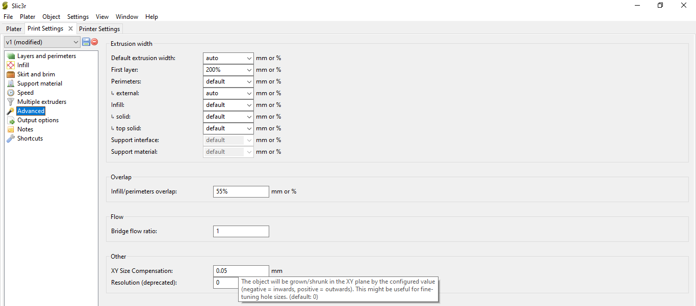
first of all I want to thank all those who have given me useful advice to solve my problem. in conclusion it seems that the problem is solved using Slic3r and going to set the value of XY SIZE COMPENSATION after several attempts and in this way I was able to solve the positioning error and the 20mm cube was printed correctly. I just have to test if this procedure works with other more complex files but I think it can work.

-
Based on your experience, is this a valid solution or can cause problems on complex prints?
-
@dvd479 It doesn't make any sense that that would fix the problem. Something else is wrong. XY size compensation is there to adjust things like hole sizes that print smaller than design size. It's essentially going to scale the print size slightly. That should not fix a layer shifting problem.
Keep looking.
-
thanks for the advice I will try to understand better what is the cause of the problem
-
in the end I realized that the problem was not due to that parameter as you told me. as solution I reduced the transition speed and everything was fine
thank you all
-
 undefined Phaedrux marked this topic as a question
-
 undefined Phaedrux has marked this topic as solved