Duet3D 1HCL - Closed Loop Controller Beta test
-
HERE'S an article I wrote (oh, god, 21 years ago) about how to tune a PID system.
It's for DC servo motor with an encoder, but all the theory applies to steppers also.
It looks like you've got EXCELLENT logging and plotting ability, so you should be able to tune fairly well.
As I've said in the past, I'm not sure what people think they are going to get out of closed-loop steppers that they don't get from open-loop steppers other than recovery if you crash your head and miss a bunch of steps.
It is not going to get you better accuracy than open-loop if you are not crashing. In fact, I'd be willing to bet that accuracy goes way down to about 2 or 3 steps even when well tuned. (I'm ready and willing to be proven wrong, this is based on decades of tuning DC servos closed-loop with a lot of different mechanical systems.)
-
@lirwin17 said in Duet3D 1HCL - Closed Loop Controller Beta test:
This graph looks good
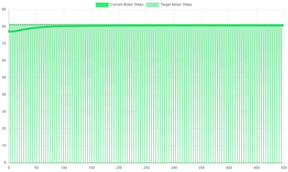
Step phase basically means the current rotational position of the motor (step phase = current step position * 90 mod 360). As the motor rotates 4 steps, I would expect to see the graph you give - it increases by 360 degrees, but rolls over once due to that mod 360.
The main point about step phase is that it roughly follows desired step phase - which it doesAaaah okay, that makes sense

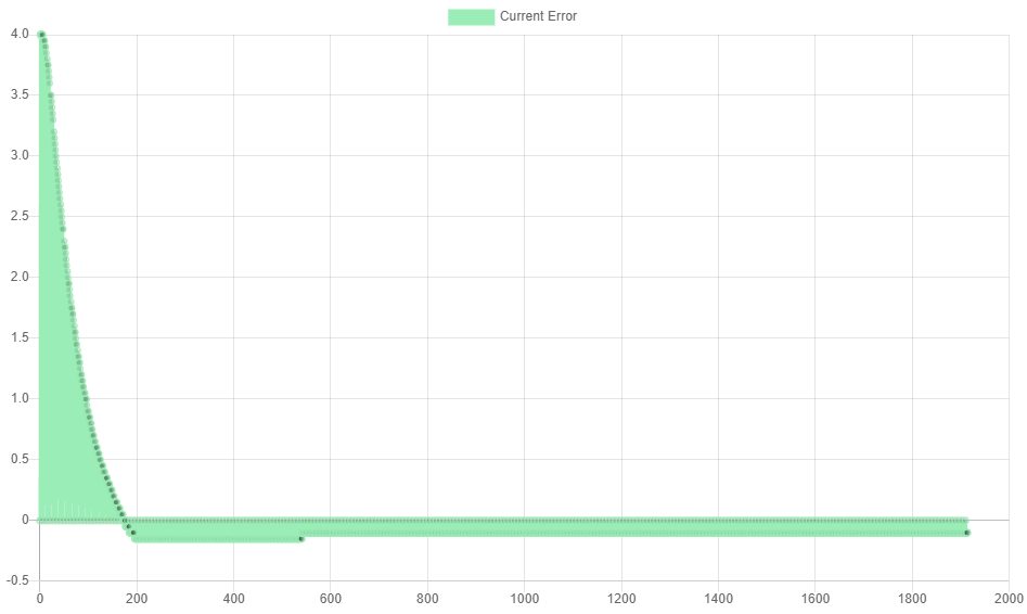
I just installed the latest firmware. The D an I parameter plots are now much more comparable to the one's in the manual, and changes in the parameters can now be seen in the plot. BTW, I often get some parameters as this zigzag lines...

R75 I0 D0.26

R75 I2000 D0.26

One more Thing:
EDIT: (I wrote mm/s instead of mm/min. Absolute no go, especially if you call yourself an engineer ) Thank's @T3P3Tony for pointing that out!
I noticed that when I put the motor in closed loop mode the maximum achievable speed is reduced to about 22000mm/min. In open loop mode I run at 36000mm/min easily.

@alankilian Thank's I will have a look!
Cheers,
Max -
HERE'S an article I wrote (oh, god, 21 years ago) about how to tune a PID system.
Looks like a great article! Thanks for linking it. I might add it to a 'further resources' section on the tuning docs

It looks like you've got EXCELLENT logging and plotting ability, so you should be able to tune fairly well.
Thankyou

As I've said in the past, I'm not sure what people think they are going to get out of closed-loop steppers that they don't get from open-loop steppers other than recovery if you crash your head and miss a bunch of steps.
You're definitely right there - but recovery like that can be a big advantage if you're dealing with especially large/costly prints. I used to do some work on a 1m^3 build volume printer that could easily churn through £1000 of filament on a single print. Because the extrusions it laid down were so big, if one was unlucky enough to slightly bend upwards into the path of the head, it could easily cause skipped steps and trash a very expensive print. IMHO Closed loop definitely makes sense as a sort of 'insurance' system in these cases - pay a little more upfront for closed loop motors to avoid the risk of trashing a £1000 print.
But closed loop does also have some other advantages:
- Less power usage, so motors run cooler. Generally when a motor is at a constant speed in closed loop mode (especially when that speed is 0) it will not be running at full current. This is especially pronounced on z-axis motors where 99% of the time the motors can be practically off, and yet they will still hold position if nudged. As opposed to an open loop system running a holding current through them all the time
- You can get higher speeds whilst maintaining accuracy! Hopefully something I might work on in my spare time is seeing just how fast a closed loop drive can run whilst still maintaining accuracy. Watch this space... Having closed loop on all your drives means you can finally answer the question "Just how fast can I run whilst maintaining an accuracy of < x steps"
It is not going to get you better accuracy than open-loop if you are not crashing. In fact, I'd be willing to bet that accuracy goes way down to about 2 or 3 steps even when well tuned. (I'm ready and willing to be proven wrong, this is based on decades of tuning DC servos closed-loop with a lot of different mechanical systems.)
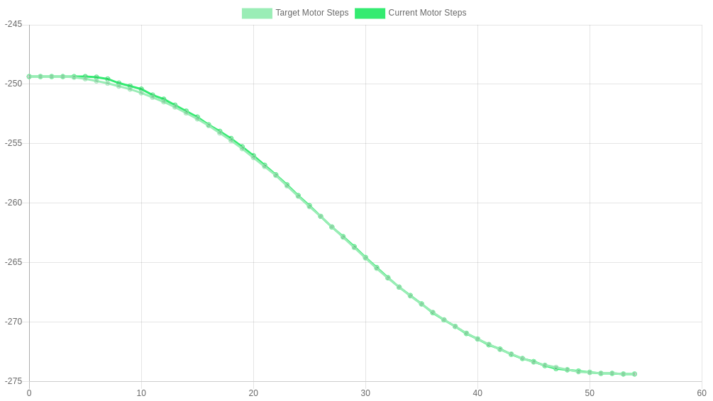
I defer to your decades of experience here, although on my Ender 3 this is the kind of movement profile I get back from a simple 5mm (~25 step) move:

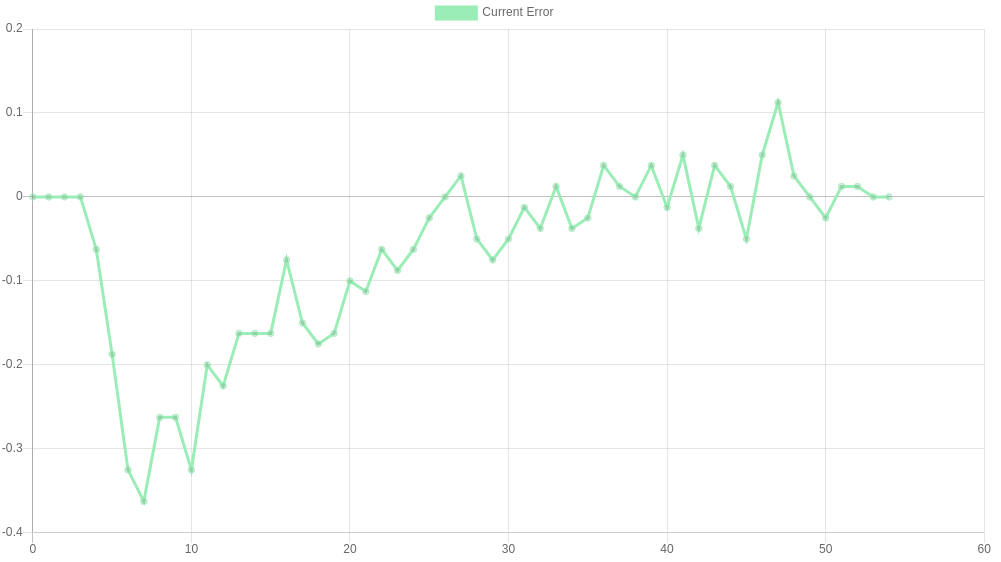
And plotting the error alone:

In the roughly 'steady state' section of the move the error very rarely exceeded 0.1 steps (both graph's y axes are in units of steps - my old high school teachers would be yelling at me to label that
 )
)
As you would expect the most error comes in the initial transient part as the acceleration increases - we're hopefully looking to eliminate that in the near future with a feed-forward mechanism, that feeds forward the next move into the control algorithm.Although as we've already said, the target audience for these probably isn't ender 3's so maybe I've made a moot point! Either way I'm really interested to see how it performs on larger axes, and whether your prediction holds true, or if we can maintain this level of performance!
-
I just installed the latest firmware. The D an I parameter plots are now much more comparable to the one's in the manual, and changes in the parameters can now be seen in the plot
Ah excellent! Sorry about that. At least the new firmware is working & out there now.
BTW, I often get some parameters as this zigzag lines...
Hmm yeah... I'll look into this. It looks like sometimes it's just reading back 0 when it should't be. I'm confident this is a issue with the data transmission between the board & DWC though - the closed loop system itself should still be performing well
 I'll get back to you on this
I noticed that when I put the motor in closed loop mode the maximum achievable speed is reduced to about 22000mm/s. In open loop mode I run at 36000mm/s easily.
I'll definitely look into this - we don't want to be reducing our top speed with closed loop!
-
@maxgyver said in Duet3D 1HCL - Closed Loop Controller Beta test:
I noticed that when I put the motor in closed loop mode the maximum achievable speed is reduced to about 22000mm/s. In open loop mode I run at 36000mm/s easily.
Can I just double check you mean 36000mm/s and not either 3600mm/s or 36000mm/m ?36000mm/s would be a "F" parameter of F2160000
-
@lirwin17 Wonderful, thanks a lot for your effort and support!
@t3p3tony said in Duet3D 1HCL - Closed Loop Controller Beta test:
Can I just double check you mean 36000mm/s and not either 3600mm/s or 36000mm/m ?36000mm/s would be a "F" parameter of F2160000
Sry rookie mistake! I did indeed mean mm/min and not mm/s

-
@lirwin17 said in Duet3D 1HCL - Closed Loop Controller Beta test:
In the roughly 'steady state' section of the move the error very rarely exceeded 0.1 steps
That's an impressive graph.
Assuming a 200 step-per-rotation motor you are showing a measurement resolution of around 0.02 steps which means you have a 10,000 counts-per-revolution encoder?
I very much doubt anyone will have such high resolution encoders except people with large (huge) budgets.
I wonder what you'd get with a more traditional stepper motor with a 300 count-per-revolution encoder on it. That's 1.2 degree-per-count, and you will not be able to get your error to less than +/- 1 count, so you have a base error of one FULL step (of 1.8 degrees) and I think you'll find you get poor print quality on any printer at that error magnitude.
It's still interesting experiment and I'm super glad you are getting the result you are with high-precision equipment. That's an excellent result so far.
And I know you're at the beginning, I don't in any way want to discourage you, I'd just like to help you understand the limitations and set expectations appropriately so people aren't disappointed in the end.
ALSO, I may be misinterpreting or misunderstanding something. I haven't been very involved at all so I'm willing to be corrected without getting any undies in a twist.

-
That's an impressive graph.
Cheers!
you are showing a measurement resolution of around 0.02 steps which means you have a 10,000 counts-per-revolution encoder
The fact I'm plotting error might make it appear like I have more resolution than I do...
As an example, imagine the motor isn't moving so I'm getting a constant encoder reading. But my target is increasing at a rate of 0.000001/s. You'd get an error reading of 0, 0.000001, 0.00002 etc... which might imply I have a (very good) resolution of 0.000001. Whereas the actual encoder reading hasn't changed so we can't tell anything about the encoder resolution. I think something along those lines is going on here
The actual encoder I'm using is a ~£30 encoder/motor combo from stepper online. Which gives an impressive 1000 CPR. The cheapest you can get is actually only ~£17 for 1000 CPR - which includes both the motor and the high-res encoder 🤯! I was pretty surprised with how cheap you could get high-res encoders like these.
You're completely right though that we need to consider how we can get the high-res required without breaking the bank, so something else that's in the works is using a hall effect 'encoder' like the AS5047D - which gives an impressive 2048 'CPR'. To be honest I have found them fairly noisy compared to the quadratures, but even that noise hasn't lead to any noticeable quality defects on my Ender 3 when compared to open loop control
One final trick up my sleeve is to dissect the CPR signal into it's individual pulses. Given that a single 'count' is actually made up of 4 pulses, we get an extra factor of 4 resolution for free!
Now technically I don't think there are any guarantees that these pulses are evenly spaced, but even if they are unevenly spaced, it still gives us an increase in resolution. (With counts, we could be up to 0.999... out, whereas even with unevenly spaced pulses, we could only ever be up to 0.4999 out (If that makes sense ))
))So dissecting the signal gives me effectively a 4000 CPR encoder for the low low price of ~£30

-
@lirwin17 said in Duet3D 1HCL - Closed Loop Controller Beta test:
One final trick up my sleeve is to dissect the CPR signal into it's individual pulses. Given that a single 'count' is actually made up of 4 pulses, we get an extra factor of 4 resolution for free!
I really don't think that's true for quadrature encoders.
The two terms used in the industry are:
- Lines per rev
- Counts per rev
An optical encoder with 100 lines on it when used in a quadrature arrangement produces 400 "edges" in the two signals in its output, so it can count 400 times per revolution.
So if your motor says 300 counts-per-rev, it's a 75-line optical encoder. If it says 1,000 counts-per-rev it's a 250-line encoder.
Of course, they COULD be saying 300 counts-per-rev and may actually mean 300 lines-per-rev but that would be a mistake on their part. Or the language has changed out from under me.
Turn the stepper one turn and see how many counts you get from your encoder-reading method and you'll know!
I'll start a new thread on an idea that I think can get you both the expected great open-loop performance of a stepper and the error-recovery of a closed-loop system without getting into all the darn PID tuning/feedforward-complexity/integral-windup/mode-changing difficulties you are about to encounter trying to implement a pure PID control of a stepper using encoder feedback.
-
Aye I'm not 100% sure of the terminology

But I've experimentally verified that this motor gives 1000 of these

full cycles per revolution, and therefore 4000 rising/falling edges per full revolution
In order to be consistent with stepperonline and some other datasheets that I've seen, we've documented 'CPR' as the number of complete cycles per revolution - which is at odds with your understanding of the terminology. This is what this period of testing is for though! So thanks for raising it! If a lot of people are getting confused, we'll look at changing the terminology that we're using to be in line with what you say. But for now, even if it's technically wrong, we'll keep the terminology as CPR so at least we're consistent with the common motor datasheets

I'll start a new thread on an idea that I think can get you both the expected great open-loop performance of a stepper and the error-recovery of a closed-loop system
I look forward to reading it!
-
I've gone down a bit of a rabbit hole looking at why it can't run at top speeds - but I think I finally have an answer!
Forgive me, but I might talk about RPM here instead of mm/min. It just makes it a bit less printer-dependant.
For reference, RPM = (mm/min) * (step/mm) * (rev/step), and here are some common conversion that we've talked about (for an average printer):
22000 mm/min = 550 RPM
36000 mm/min = 900 RPMIn theory, the maximum speed is given by the PID loop frequency. Each iteration of the PID loop can command the motor to take 1 step (=rotate 0.005 degs). The PID loop currently runs at 12000 Hz.
This means that the theoretical max speed is 12000 x 0.005 x 60=3600 RPM.Why then are we topping out at ~900 RPM (measured on my Ender 3, other's results may be different)
The answer is how long it takes to communicate the new motor currents to the driver ICs that we use.
At the minute, this takes ~0.064ms. At low RPMs, this is negligible. But at high RPMs, it means the motor has moved on a significant amount between deciding what current to set, and actually setting that current. At my max speed of 900RPM, it's moved on a whole 0.2 steps. We should be able to fix this by looking at the current RPM and 'predicting' how much the motor will have moved by the time the currents have been sent.Thanks for pointing this out! It would be useful if I could gauge just how much of an issue this is. Would the current top speed be an issue for you? Or is it just a nice-to-have? If anyone else would have issues with this limitation, please do say

This feedback will then impact our decision on what to focus on improving next
-
@lirwin17 said in Duet3D 1HCL - Closed Loop Controller Beta test:
Thanks for pointing this out! It would be useful if I could gauge just how much of an issue this is. Would the current top speed be an issue for you? Or is it just a nice-to-have? If anyone else would have issues with this limitation, please do say
For me, the whole point of switching to closed loop was to increase speed and reliability. In open loop my printer starts skipping steps at around 900 RPM (36000mm/min). During printing, I limit the travel speed to 24000 mm/s just to be on the safe side. So if it can reliably run at 900 RPM in closed loop, it would be okay for me. Everything more than that would be a nice to have.

-
Okay, I have to revise my previous statement about the max. achievable speeds:
In fact my open loop travel speed is set to 600 mm/s (36000 mm/min or 900 RPM) and this already includes a 25% safety margin.
I just did some speed testing on my printer. I achieved speeds up to 1500 mm/s (2250 RPM) on a single axis without problems. I did not test the performance with multiple axis moving with other stuff like CoreXY interpolation and Z height adjustment going on. But it is an indicator of what the motor/driver is capable of in open loop.
In closed loop mode, my motor sound is kind of "wobbly", like it is slightly accelerating and decelerating on every turn. The "wobbly" sound becomes more noticeable with increasing speed. The Motor loses its position when the speed is over 400 mm/s (600 RPM).
Right now my setup is slower in closed loop than in open loop

-Max
-
@maxgyver said in Duet3D 1HCL - Closed Loop Controller Beta test:
In closed loop mode, my motor sound is kind of "wobbly", like it is slightly accelerating and decelerating on every turn. The "wobbly" sound becomes more noticeable with increasing speed.
That sounds just like what I measured using a commercial external closed-loop stepper controller in THIS thread.
-
@alankilian that language is consistent with my understanding too, although the encoder and reference material I use has lines = pulses, and counts = changes.
So a 600ppr encoder has 2400cpr.
Same principles all the same.
-
@t3p3tony I have my firmware updated on both the 6HC and the tool board, I type in command M122 B50 and I get:
M122 B50
Diagnostics for board 50:
Duet EXP1HCL firmware version 3.4.0beta3 (2021-08-24 14:56:43)
Bootloader ID: SAME5x bootloader version 2.4beta (2021-07-23)
Never used RAM 52992, free system stack 2582 words
Tasks: Move(notifyWait,0.0%,126) HEAT(notifyWait,0.0%,108) CanAsync(notifyWait,0.0%,70) CanRecv(notifyWait,0.0%,79) CanClock(notifyWait,0.0%,72) TMC(notifyWait,15.0%,28) CLSend(notifyWait,0.0%,150) CLData(notifyWait,0.0%,142) MAIN(running,83.0%,437) IDLE(ready,0.0%,39) AIN(notifyWait,1.9%,265), total 100.0%
Last reset 00:12:21 ago, cause: software
Last software reset time unknown, reason: HardFault bfarValid precise, available RAM 51580, slot 0
Software reset code 0x0060 HFSR 0x40000000 CFSR 0x00008200 ICSR 0x00430803 BFAR 0x20030008 SP 0x2001eba8 Task MAIN Freestk 531 ok
Stack: 00000000 00000000 00000002 20030000 00030f39 0001b8f9 0001ea4c 41000000 bf800000 00000000 533c0605 04001200 a808a700 06420000 c3210828 19a21429 50708239 5d000040 2a60041c 5dd40122 4143051f 41200000 41c22c02 4142f6d6 20000010 0002699b 00000002
Closed loop enabled: yes, live status: 0x4, encoder type linearQuadrature, pre-error threshold: 20.000000, error threshold: 100.000000, coil A polarity: +, coil B polarity: -, tuning: 0, tuning error: 0x1f, position -1515870812, raw count = 65535, collecting data: no, ultimateGain=0.000000, oscillationPeriod=0.000000
Driver 0: position -50588, 106.5 steps/mm, standstill, reads 53855, writes 28 timeouts 0, SG min/max 0/455, steps req 62302 done 17087
Moves scheduled 5, completed 5, in progress 0, hiccups 0, step errors 0, maxPrep 25, maxOverdue 0, maxInc 0, mcErrs 0, gcmErrs 0
Peak sync jitter -4/5, peak Rx sync delay 180, resyncs 0/0, no step interrupt scheduled
VIN: 24.3V, V12: 12.2V
MCU temperature: min 27.4C, current 28.4C, max 28.4C
Ticks since heat task active 165, ADC conversions started 734738, completed 734737, timed out 0, errs 0
Last sensors broadcast 0x00000000 found 0 170 ticks ago, loop time 0
CAN messages queued 5973, send timeouts 0, received 6695, lost 0, free buffers 37, min 37, error reg 0
dup 0, oos 0/0/0/0, bm 0, wbm 0, rxMotionDelay 292, adv 37084/37194 -
@supertb1 ; Drives
G4 S1 ;wait for expansion boards to start
M569.1 P50.0 S1 T2 C20 E20 R100 I0 D0 ; Configure the 1HCL board at CAN address 50 with a quadrature encoder on the motor shaft that has 20 steps per motor full step.
M569.1 P51.0 S1 T2 C20 E20 R100 I0 D0 ; Configure the 1HCL board at CAN address 51 with a quadrature encoder on the motor shaft that has 20 steps per motor full step.
M569 P50.0 D4 S1 ; Configure the motor on the 1HCL at can address 50 as being in closed-loop drive mode (D4), Open loop (D2) and not reversed (S1) X axis
M569 P51.0 D2 S1 ; Configure the motor on the 1HCL at can address 51 as being in closed-loop drive mode (D4), Open loop (D2) and not reversed (S1) Y axis
M569 P0.0 S1 ; physical drive 0.0 goes forwards Z 1-2 axis
M569 P0.4 S1 ; physical drive 0.4 goes forwards Extruder
M584 X50.0 Y51.0 Z0.0:0.1 E0.4 ; set drive mapping
M671 X-122.25:689.20 Y0:0 S3.0 ; leadscrews at left (connected to Z0) and right (connected to Z1) of X axis
M350 X32 Y32 Z32 E16 I1 ; configure microstepping with interpolation
M92 X106.5 Y257 Z795.00 E339.00 ; set steps per mm
M566 X900.00 Y900.00 Z60.00 E120.00 ; set maximum instantaneous speed changes (mm/min)
M203 X6000.00 Y6000.00 Z180.00 E1200.00 ; set maximum speeds (mm/min)
M201 X500.00 Y500.00 Z20.00 E250.00 ; set accelerations (mm/s^2)
M906 X1000 Y3000 Z3000 E800 I30 ; set motor currents (mA) and motor idle factor in per cent
M84 S30 ; Set idle timeout
M917 X0 Y0 ; Set the closed loop axes to have a holding current of zero -
@supertb1 Product Model 42A03EC
Step Angle 1.8°±5% (full step no-load)
Rated Current 2.0 A
Holding Torque 0.3NM(42.5oz.in)
Encoder Resolution 4000ppr
Phase Resistance 1.6Ohm ± 10%
Phase Inductance 1.9mH ± 20%
Rotor Inertia 77g.cm²
Moto Size 424269mm
Shaft Diameter 8mm
Number of Leads 4
Description of Wire: Red (A+), Black (A-), Yellow(B+), Blue (B-)(new version); -
@supertb1 homex.g
; called to home the X axis
;
; generated by RepRapFirmware Configuration Tool v3.2.3 on Mon Mar 08 2021 08:53:31 GMT-0600 (Central Standard Time)
M569 P50.0 D0 ; Turn off closed loopG91 ; relative positioning
G1 H2 Z5 F6000 ; lift Z relative to current position
G1 H1 X-240 F3000 ; move quickly to X axis endstop and stop there (first pass)
G1 H2 X5 F6000 ; go back a few mm
G1 H1 X-240 F240 ; move slowly to X axis endstop once more (second pass)G90 ; absolute positioning
G1 X50 F3000 ; Move to a known-safe position
M400 ; Wait for the move to complete
G4 P500 ; Wait for the motor to settle
M569 P50.0 D4 ; Turn closed loop back on
M569.6 P50.0 V31 ; Perform the tuning manoeuvres for a quadrature encoder
G1 X0 ; Move back to X0G1 H2 Z0 F6000 ; lower Z again
-
@t3p3tony sorry about the multiple posts but it seems the posts are limited in size to 50 or 60 lines... is there anything else I can give you to make this easier?