HELP! Duet 2 WiFi Configuration and DWC Upload???
-
After a couple hours of tuning I got this height map. Do you think its good enough, or should i keep adjusting the bed and do another height map?
This was done with my heaters on
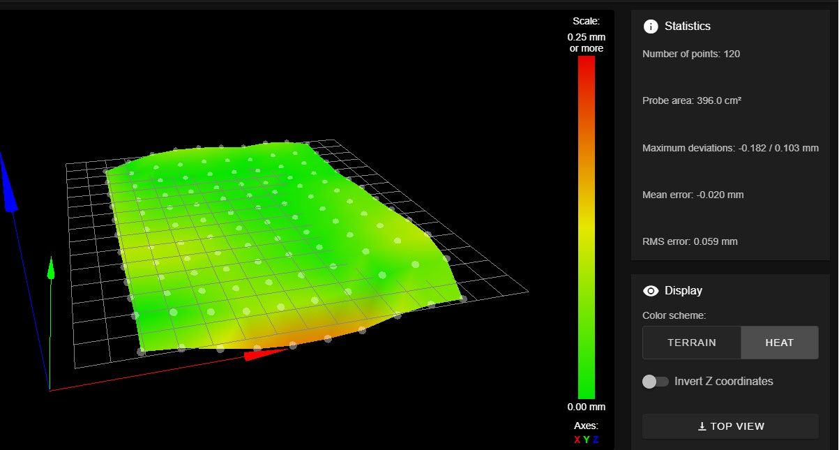
And this was the one I did with the heaters off
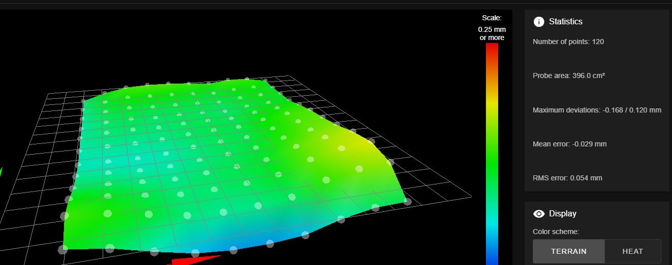
Thanks,
-Carson
-
Those look pretty good actually. If you want to test the effectiveness of the mesh compensation try printing something like this
-
Ok. I can print that now, right? So, like no more setting up the mesh compensation, or saving it to the SD Card?
What is the Z=0 datum for? Is that just if I want to use a different height map?
Before I checked my points with the probe, I would home Z and then bring the bed down 6.5mm and command the probe. Is that the Z datum? Z at 0 or at 6.5?The only other thing on the Mesh Bed Compensation page is Compensation Taper. Do I need to mess with that at all, or no?
I found this a while back. Does it apply to me? or is it the same thing I'm doing currently?
https://duet3d.dozuki.com/Wiki/Setting_up_automatic_probing_of_the_print_bed
Thanks,
-Carson
-
@pcnoobneedsmajorhelp said in HELP! Duet 2 WiFi Configuration and DWC Upload???:
Ok. I can print that now, right? So, like no more setting up the mesh compensation, or saving it to the SD Card?
Yes you should be ready to go. The mesh is saved to the SD card as soon as it's created with G29. It's stored as heightmap.csv in the system folder.
@pcnoobneedsmajorhelp said in HELP! Duet 2 WiFi Configuration and DWC Upload???:
What is the Z=0 datum for?
A datum is a fixed reference point. So in this context, all it means is the position where Z=0. In other words, it's where your bed surface is. The Z axis position displayed is the distance between the bed and the nozzle tip. This gets set by the probe when you home Z.
@pcnoobneedsmajorhelp said in HELP! Duet 2 WiFi Configuration and DWC Upload???:
Compensation Taper. Do I need to mess with that at all, or no?
That's up to you. It reduces the amount of compensation applied over a set amount of height. So in your case the bed is fairly flat and the deviations between low spots and high spots is pretty small. You could set a taper off value of 20mm so that by the time the print reaches 20mm it's not compensating anymore. Try it both ways when printing a simple tall tower and see what it does differently. You probably won't be able to tell.
@pcnoobneedsmajorhelp said in HELP! Duet 2 WiFi Configuration and DWC Upload???:
https://duet3d.dozuki.com/Wiki/Setting_up_automatic_probing_of_the_print_bed
You're basically already doing that using G29.
-
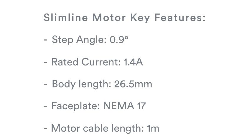
So before I do my test print (since I installed the new motor) I wanted to recheck my E-steps, so I did, and It's all good. Then I rechecked my max feed rate, and it went from 5.98 to 1.45mm/s. Is that going to be enough speed? If not, is it kosher to increase the motor current past 80%, or would it burn out on a long print/fry anything? Right now my new motor's current is set to 1200mA
New Motor Specs
Old Motor test results
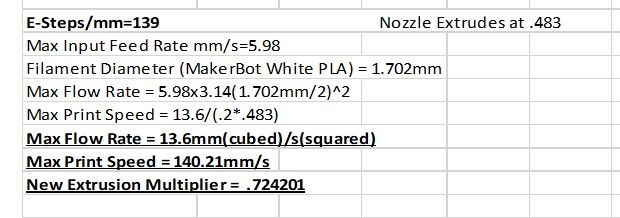
Thanks,
-Carson
-
If the new motor has much lower torque than the previous one that might explain it. Usually the shorter the motor the lower the torque.
Increasing the current past 80% is possible but heat becomes an issue and there are diminishing returns. Ultimately it won't help that much.
How did you measure the max flow rate?
-
Max Flow Rate = Max Input Feed rate * pi * (Filament Diameter/2)^2
Do you think 1.45 will be fine though? if not I'll get a new motor
-
That seems a bit low, but small pancake motors like that aren't really meant to be power houses. Small, light, compact for geared direct drive extruders. Shouldn't really be a problem if printing with a 0.4mm nozzle and 0.2mm layer height at 50mm/s. Anything more than that and you'd be possibly skipping steps.
How did you determine 1.45mm/s was the max feed rate you could reach? What kind of filament and what temp?
-
I used to print at 213 but then I added the all metal Hotend with a copper coated block. So now, I print at 218 and have been getting really good results (with PLA).
The process I used was very caveman haha. After lowering the bed to about 150mm, I set the feed amount starting at 10mm and I set the feed rate at 1mm/s. I increase the feed rate by .25mm increments until it starts to skip, then I back down in .05mm increments until the skipping stops, then to .01 increments. I then run whatever that speed is (in this case 1.45mm/s), at 30mm of feed amount, and if I get no skipping again, I'll bump it up to 100mm feed amount. If it can safely handle 100mm at that speed without skipping then that's my max feed rate.
The only other thing that comes to mind would be the gear ratio not sure if It's 3:1 or not
-
@pcnoobneedsmajorhelp said in HELP! Duet 2 WiFi Configuration and DWC Upload???:
The only other thing that comes to mind would be the gear ratio not sure if It's 3:1 or not
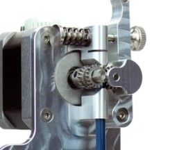
Is it this microswiss extruder? https://store.micro-swiss.com/products/micro-swiss-direct-drive-extruder
If so there is no gearing at all, which kind of explains the lack of torque. Those slim line motors are really only good for a geared extruder that gain them some torque back.
-
Yeah I'm pretty sure it's the in the slim line motor family.
Would you then suggest I swap out the gearless Idler/Driver for a geared Idler/Driver? Is there any downside to that, given that I have a direct drive system?
If I did swap them should I get a better stepper driver while I'm at it?
-
A geared extruder is always preferable to an ungeared one. More torque and better resolution. That slim motor would be more suitable to a geared extruder. But as I said above, if you don't plan on trying to push a lot of plastic very quickly you should be fine as it is. Otherwise if you want to go beyond 50mm/s 0.4 width 0.2 layers you'd probably want either a geared extruder or a larger motor.
-
Ok. If a motor is a 2 phase motor and the rated current per phase is .8A, then that motor would be a 1.6 motor, correct? (Rated current 1.6[1.6 * .85= 1.28] set motor current in config.g for 1280mA)
-
-
so as you said in a previous reply this I s NOT a geared drive? although to me it looks geared. just want to be clear
Yeah I read that page yesterday but it didn't answer my question that's why I was asking
-
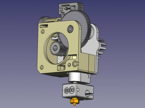
I don't think that's geared. The motor shaft is in direct contact with the filament path. A geared extruder would have a small gear on the shaft and then a larger gear in contact with it and driving the hobb to drive the filament.
for example:
-
Ah ok got it.
but the reason I was asking about the current ratings in the first reply was because I'm looking at 5 potential motors and some of them are rated 1.5 and some are rated .8/phase and they have really similar mN.m ratings and I just wanted to know, before I buy the one that I think is the best.
Thanks,
-Carson
-
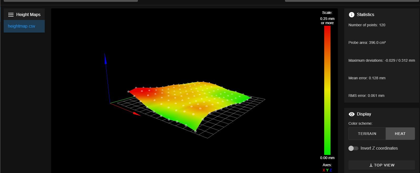
How do I know if my mesh compensation is enabled? I did a test print and it was way off even though the map said it was super flat. So of course before checking if it was enabled, I messed with it and although the Mean and Deviations are worse now, I want to see if it's actually enabled before I run another test print.
Here's what my new map looks like (HORRIBLE compared to my last one bummed out
 )
)
-
Send M122 and check for "compensation in use: mesh"
-
