HELP! Duet 2 WiFi Configuration and DWC Upload???
-
For the prime line, where do you want it to start and end? Physically jog the nozzle to where you want it to start and end, and make note to the XY coordinates, then we can place those in the prime line.
For the end gcode, I don't see anything that would be moving it a large amount at the end of the print. It looks like it should be doing a retraction and then a small 5mm diagonal move to wipe the nozzle and then raise it. Can you maybe make a video showing what it's doing at the end of the print?
-
@phaedrux
Videos for start and end of prints as they are currently
https://www.dropbox.com/sh/urqhwgr6phs2uty/AAC8QKXjih9UCh5PN5P1vy8ia?dl=0
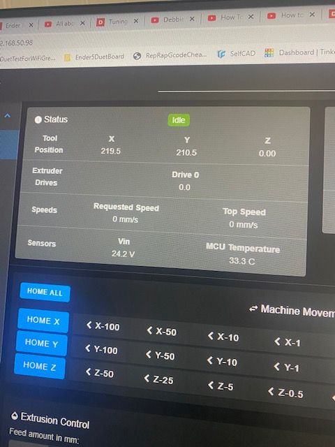
Picture of new coordinates for the start of the prime line
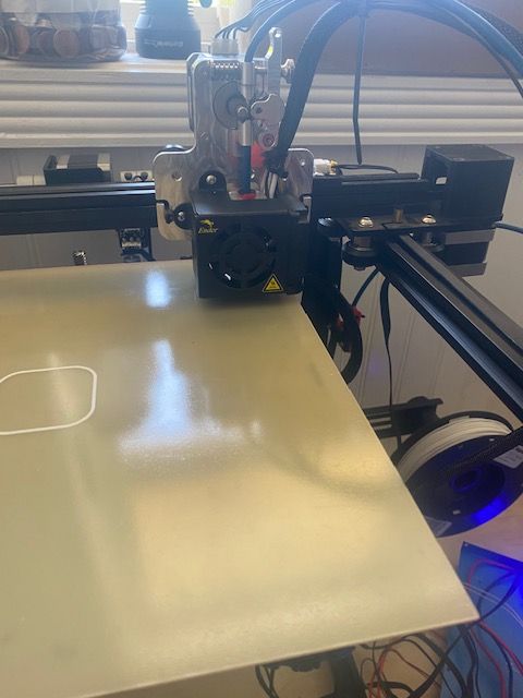
Picture of printer head position for new coordinates to be entered^
-
Here's what I plugged in (what I think it might be).
-I won't run anything until I get the okay from you. Just wanted to try and be proactive.
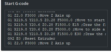
New Start G-code
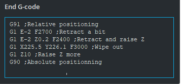
New End G-code 1 of 2
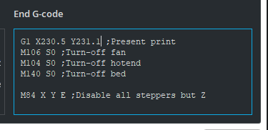
New End G-code 2 of 2
-
The prime line location looks good.
The end gcode has a problem though. You've changed the small wipe move of 5mm to a massive 230mm move. That's not what you want to happen.
The "present print" bit could be removed entirely. Is that below the first part? I hadn't see that before. That might have been what was causing the crashing. That move would make more sense for a cartesian i3 style printer with a bed that moves back and forth. The idea being that it will slide the bed forwards for you to get at the print. In this case you really just want the print head to move out of the way. The safest way to do that would be to replace
G1 230 Y230 ; present printwithG28 X Ywhich will just home the X and Y axis to get the print head out of the way. -
Yes, the second End G-code picture is below it when you scroll down
Ok. I've fixed a few things. Let's see how this is.
Start and End (Top Half)

Start and End (Bottom Half)

If all this looks good, I'll run another test print
Thanks,
-Carson
-
Yes that looks better.
-
Everything looks good. After I get home from work tomorrow, I'll do a few different tests, other than the cube and just check everything out to be sure.
Thanks again for all your help! I couldn't have done it without you!
-A very Grateful Printer, Carson
-
So I'm back.
3 questions.
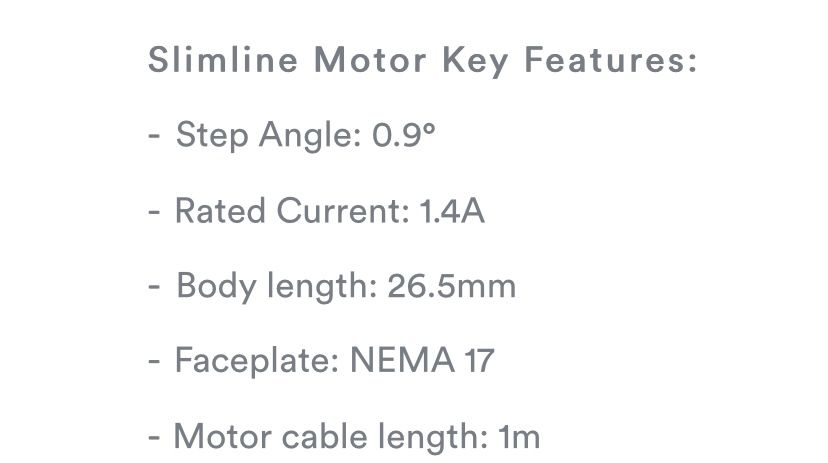
- I swapped my extruder stepper motor with a .9° pancake. What settings do I need to change in my config file?
- When I pause a print it crashes into the front left corner. What do I need to change? the G90 command?
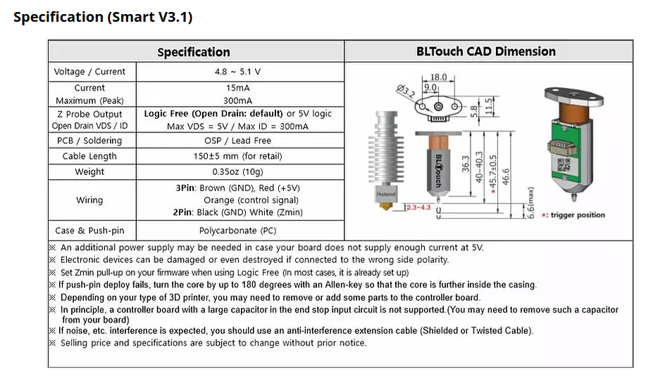
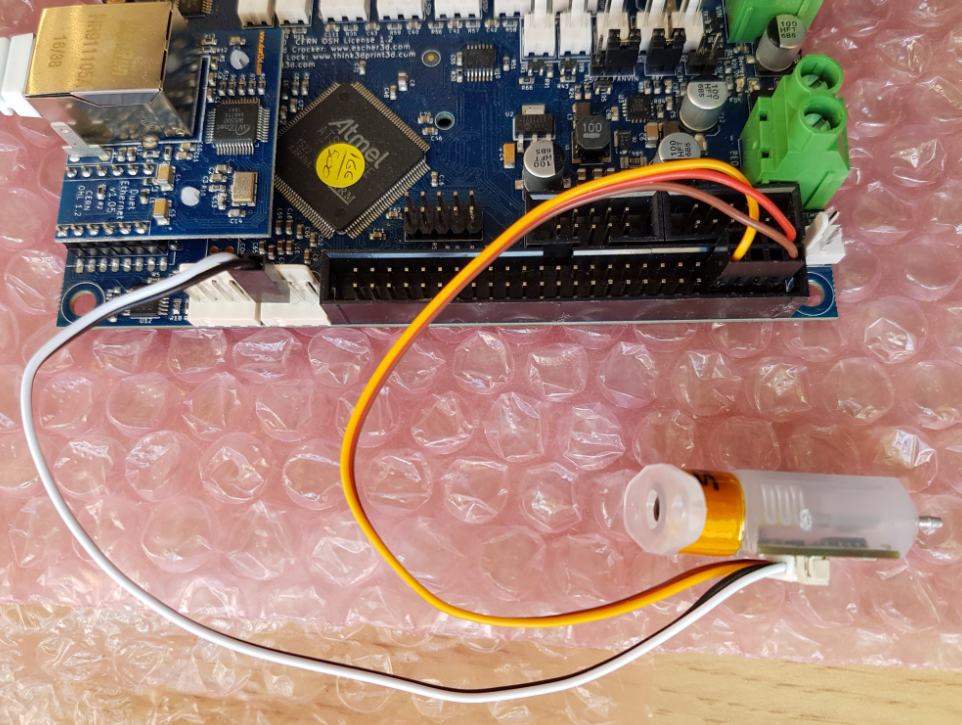
- I am ready to set up the BL Touch. How do I set it up in the config file? It's physically installed on the fan shroud, but I don't know what or if I need to set the offset. I also don't know where to plug it in on the duet. I have the Black and White wired to the Z Endstop. Where do I plug the yellow red and blue connector into?
ERROR
Something went wrong while parsing server response^ I keep getting this when I try and upload screenshots of my files. Until I get it fixed let me know what you need and I can relay the info.
Thanks,
-Carson
-
@phaedrux
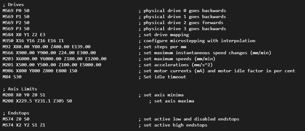
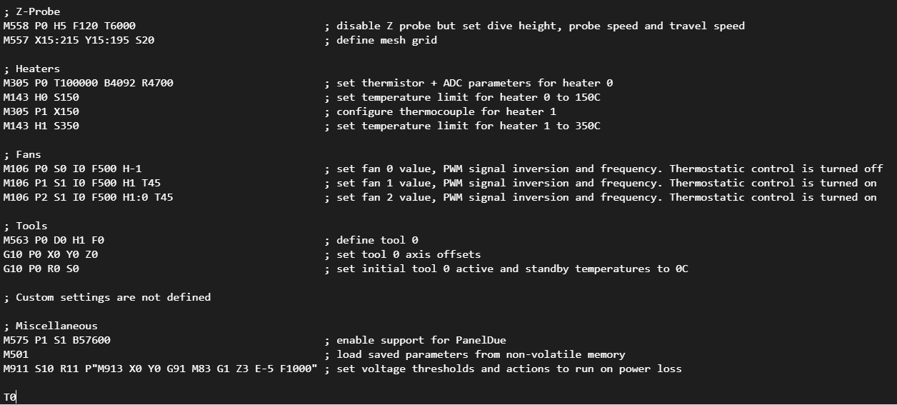
Fixed it. Here are screenshots of my files as they are currently set

-
For the extruder changing to 0.9 degree from 1.8 degree means that you would double your steps per mm. If you were already using a 0.9 motor you wouldn't change anything.
For your pause.g if it's hitting the edge you can slightly adjust the G1 X0 Y0 to be G1 X10 Y10 to give it some space. But if it can't safely reach x0 y0 then your M208 maxima might be a bit off.
For the BLTouch you need this in config.g
; Z-Probe
M307 H3 A-1 C-1 D-1                     ; disable heater on PWM channel for BLTouch
M558 P9 H5 F120 T6000                   ; set Z probe type to bltouch and the dive height + speeds
G31 P500 X0 Y0 Z2.5                     ; set Z probe trigger value, offset and trigger height
M557 X15:215 Y15:195 S20                ; define mesh grid
You'll need to check config-override.g to any
M307 H3lines and delete them if they exist.And you'll need to create two macro files in the /sys folder for deploy and retract commands to control the pin.
; deployprobe.g
; called to deploy a physical Z probe
;
; generated by RepRapFirmware Configuration Tool v3.2.3 on Sat May 22 2021 10:19:48 GMT-0600 (Central Standard Time)
M280 P3 S10 I1 ; deploy BLTouch
; retractprobe.g ; called to retract a physical Z probe ; ; generated by RepRapFirmware Configuration Tool v3.2.3 on Sat May 22 2021 10:20:08 GMT-0600 (Central Standard Time) M280 P3 S90 I1 ; retract BLTouchFor wiring it up you should follow this:
-
When I was checking the new e-steps I noticed it was skipping so I tried to loosen/tighten the tension, and then I took out the filament and the same thing happened. Does this mean this particular motor doesn't have enough torque to support the extruder?
https://www.dropbox.com/s/dw34eyf572cj4vj/Skipping Motor.MOV?dl=0
-
Do you have to have the specs of the motor? It may need more current than the previous motor. The rule of thumb is to use ~60-80% of the rated motor current.
So if the motor is rated as 1amp (aka 1000ma) then you would use 600 to 800 ma in the M906 command to set the current.
-
-
Oh also should the tip of the BLTouch probe be at the same height as the tip of my nozzle in relation to the bed?
-
@pcnoobneedsmajorhelp No, or you risk crashing the BLT
IIRC the bottom of the main body of the BLT, not the probe should be 4-5mm higher than the nozzle -
-
Basically when the probe is extended it should be lower than the nozzle and when retracted as illustrated 3-4mm higher than the tip of the nozzle.
-
Ok. So.
-I changed my current to 1200 for the extruder motor
-I changed my pause.g file.
-I changed the confi.g file for the probe, deleted the M307 H3 line in config-override.g, created the deploy and retract macros, and wired everything up correctly. The tip of the probe is about 3mm above the tip of my nozzle. (Do these changes stay the same for the 2.05 firmware version?)What's next?
-I feel like I read something about setting the Z probe height in the config.g file or in bed.g or homeZ?
-How do I set up the mesh bed compensation?
-I removed the original Z endstop, is that right?
-and lastly, do I have to change any settings in Cura? -
@pcnoobneedsmajorhelp said in HELP! Duet 2 WiFi Configuration and DWC Upload???:
-I feel like I read something about setting the Z probe height in the config.g file or in bed.g or homeZ?
Yes you will need to calibrate the trigger height of the probe. Basically telling the firmware how far the nozzle is from the bed when it triggers. Without this it doesn't know where Z0 is.
You also need to tell it how far away the probe is from the nozzle in X and Y.
The instructions are here: https://duet3d.dozuki.com/Wiki/Test_and_calibrate_the_Z_probe
-How do I set up the mesh bed compensation?
Once the probe is working see here: https://duet3d.dozuki.com/Wiki/Using_mesh_bed_compensation
-I removed the original Z endstop, is that right?
Generally, yes. Homing Z would be done with the probe instead. You will need to edit your homing files to use the probe now.
Instead of
G1 H1 Z-400you would haveG1 X150 Y150 F6000 ; move probe to center of bed G30 ; probe the bed to determine Z0-and lastly, do I have to change any settings in Cura?
No
-
@pcnoobneedsmajorhelp
Z Probe
Read these, they are useful.
https://duet3d.dozuki.com/Wiki/Connecting_a_Z_probe#Section_Commissioning_Testing_RepRapFirmware_Num_3
and all of this or most of it.
https://duet3d.dozuki.com/Wiki/Test_and_calibrate_the_Z_probe#Section_Dynamic_testDo you want to post your config.g for a sanity check?
P.
EDIT: @Phaedrux to the rescue!
