stepper precision
-
enough for now, need to stiffen this coupling
-
If you have it available somewhere you can use some 6mm/8mm inner diameter petrol hose. The rubber kind with a (cotton?) braid as reinforcement embedded in the rubber. Due to the reinforcement that stuff is quite stiff in rotation, due to it being rubber a hose clamp clamps it stiffly around a shaft.
I stumbled over M569.1 in the G-code reference today. Is that already implemented?
In case you have to return the encoder before finishing you tests: I probably have some 2500-line incremental encoders with quadrature output (10000 pulses/rev) lying around over here somewhere. I can miss one or two. If I can find them..
(you may think your mancave is a mess, but I am fairly certain I win that battle) -
@DaBit said in stepper precision:
If you have it available somewhere you can use some 6mm/8mm inner diameter petrol hose. The rubber kind with a (cotton?) braid as reinforcement embedded in the rubber. Due to the reinforcement that stuff is quite stiff in rotation, due to it being rubber a hose clamp clamps it stiffly around a shaft.
no way to get it as most shops are closed but I expect monday to arrive the aluminium 5-5 that I'll drill on one side to 6mm should work ok I'll try to put it in a lathe
I stumbled over M569.1 in the G-code reference today. Is that already implemented?
no idea
In case you have to return the encoder before finishing you tests: I probably have some 2500-line incremental encoders with quadrature output (10000 pulses/rev) lying around over here somewhere. I can miss one or two. If I can find them..
Thanks :), the idea with 16bit was to get really precise data about microstepping, I think I'll manage to get all the testing I want before I return it
(you may think your mancave is a mess, but I am fairly certain I win that battle)
uh, I doubt, not 'cause my mancave is normally total chaos but because I purchased a house in 2019 and started renovating and it features a small 50m2 guest house (with 50m2 under roof storage too) in the yard that I planned to use as my new mancave, and since the plan was to move in summer 2020 I started converting my current mancave (a 20m2 room 5m high in appartment) into storage room, so I'm now working from something one could call storage and not mancave, stuff falls on me non stop, if I move too fast stuff falls of my desk, keyboard drawer etc .. very nasty place to work, not at all "artistic chaos", more like "garbage dump"
 ... and due to #$%^#^% we did not move yet so .. house is still being renovated and I work berried in "garbage"
  .. not something I am happy with
-
alu coupling mounted.. repeating the measurements..
-
Fingers crossed...
-
@DaBit initially the "vibrations" are still there (1/16, closed loop, s42b)
AVERAGE:  449 ,  205.2
221
221
221
222
222
222
222
221
222
221
AVERAGE:  450 ,  221.5
234
234
234
234
234
235
234
235
234
234
AVERAGE:  451 ,  234.2
256
256
255
256
255
256
256
255
256
256
AVERAGE:  452 ,  255.7
after it finish we'll check the positional error but.. imho this S42B is a complete and utter POS

this is measured second after step!!! so the vibration is either $#^#@ motor or S42B dancing around the target location (same vibration 10sec after step too)
-
@arhi Do you mean that the values you are reading are changing by plus or minus one if you read the encoder a lot of times?
Because that's not unusual for such a high-resolution encoder where one count is 0.005-degrees of angle.
Also, it's possible to get a +/- 1 oscillation if you stop RIGHT ON the edge of a line and move an infinitesimally-small angle. But I wouldn't expect that on every step. You showed three steps where it was doing it, so I think it's the controller.
Hey, depending on how the s42b reads the TLE5012B angle sensor it can really only get either 15 bits or 16 bits of value from the angle of the magnet, so your encoder might have twice the resolution of the controller.
15 bit representation of absolute angle value on the output (resolution of 0.01°)
16 bit representation of sine / cosine values on the interface
So I think the controller is doing about as well as it can.
-

-
@alankilian said in stepper precision:
@arhi Do you mean that the values you are reading are changing by plus or minus one if you read the encoder a lot of times?
Yes. But if I turn motor off that does not happen.
Also, it's possible to get a +/- 1 oscillation if you stop RIGHT ON the edge of a line and move an infinitesimally-small angle. But I wouldn't expect that on every step. You showed three steps where it was doing it, so I think it's the controller.
Exactly, happens almost every time, and with TLC for e.g. it was not happening (we'll see how it will behave with alu coupler) and when I turn the driver off it does not happen so it's def "dancing", not by much but..
So I think the controller is doing about as well as it can.
WRT "dancing", probably. WRT "position", not really

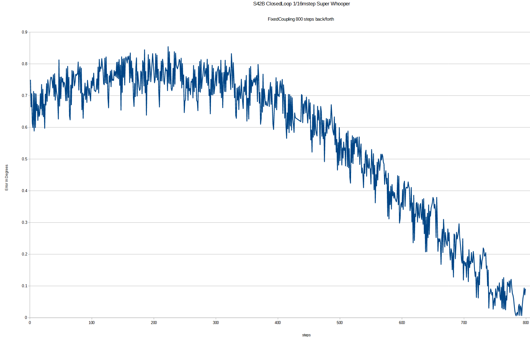
The LCD is not showing errors, the "error" led (lost step) is off .. and 800 steps in forward and then 800 back we have error of 0.75° .. that's HUGE IMHO especially considering 1step/second speed -
@arhi said in stepper precision:
The LCD is not showing errors, the "error" led (lost step) is off .. and 800 steps in forward and then 800 back we have error of 0.75° .. that's HUGE IMHO especially considering 1step/second speed
If you were to configure the stepper (if possible) to only use whole steps would the error go away?
Frederick
-
That's half a step. I would expect a simple open-loop motor to perform better.
On the other hand, I am sure you can interpolate a single rotating magnet with 15 bit resolution, but resolution != precision.
A long time ago I did approximately the same for a customer, but back then it was an entire board with an FPGA, Burr-Brown ADC's and discrete analog frontend. We got ~9 bits of accuracy, the rest got lost in noise and nonlinearities. -
@fcwilt said in stepper precision:
@arhi said in stepper precision:
The LCD is not showing errors, the "error" led (lost step) is off .. and 800 steps in forward and then 800 back we have error of 0.75° .. that's HUGE IMHO especially considering 1step/second speed
If you were to configure the stepper (if possible) to only use whole steps would the error go away?
Frederick
with S42B - not that I know ... I'll do as much tests with S42B first (open and closed loop) then moving to 2208 with different motors ... I'll add graphs as I go trough different tests but as you can see it is all rather slow as I'm doing 1step/sec
-
@DaBit said in stepper precision:
That's half a step. I would expect a simple open-loop motor to perform better.
I heard from some ppl S42B is awesome, but from some other I heard they are POS .. so I decided to try them out .. so far I already decided I will not be using them in my projects
On the other hand, I am sure you can interpolate a single rotating magnet with 15 bit resolution, but resolution != precision.
yeah but it does "calibration", moves a circle and records magnet readings at halfsteps I think so the resolution here should help a lot with precision.. but..
-
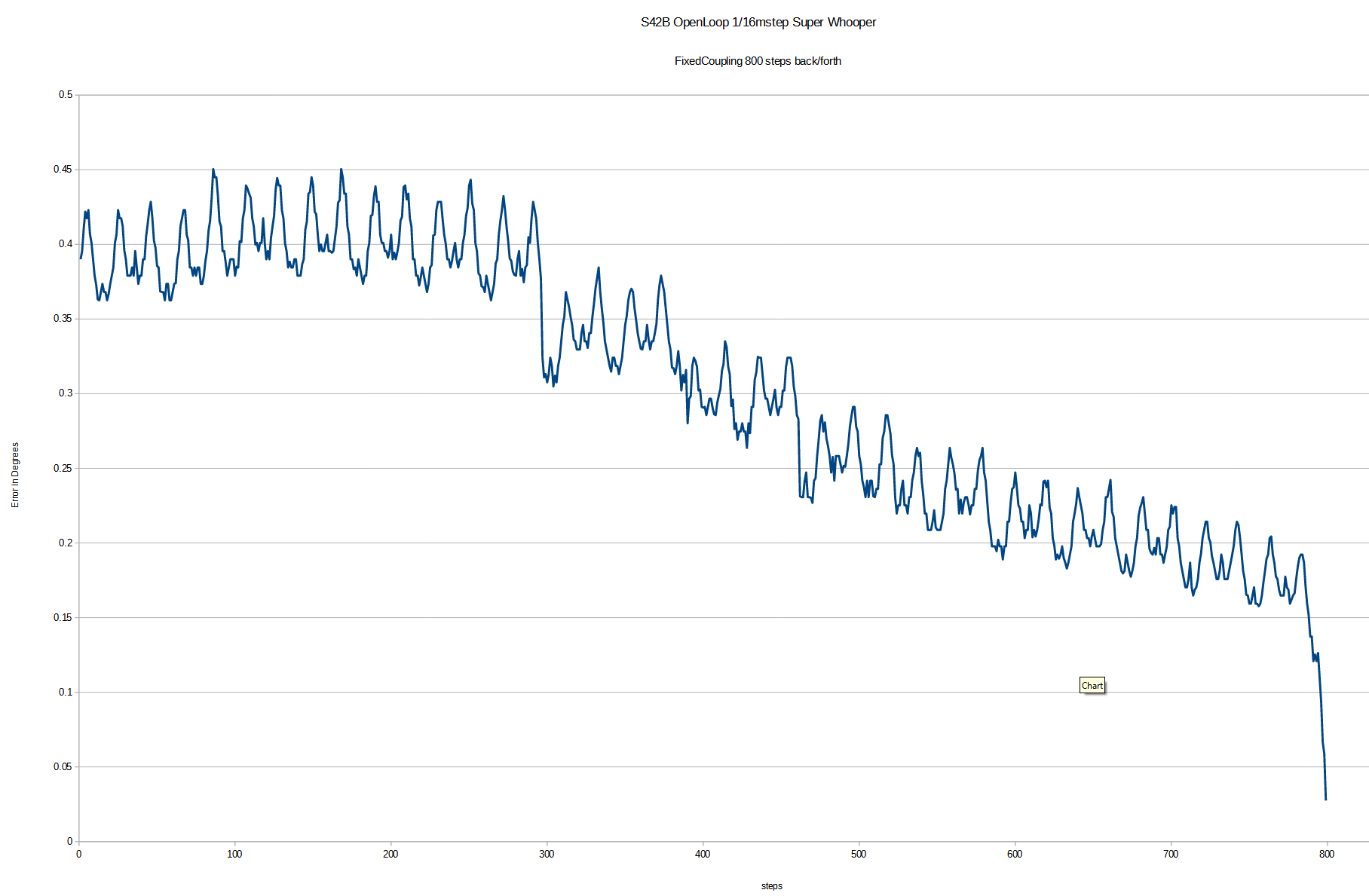
what I seen on number of reports on-line, open-loop works better than closed loop with S42B


-
That calibration only cancels fixed nonlinearities (and adds stepper imprecision). A slight magnetic short after calibration of changing operating point of the sensor due to temperature is not cancelled.
-
@DaBit said in stepper precision:
That calibration only cancels fixed nonlinearities (and adds stepper imprecision). A slight magnetic short after calibration of changing operating point of the sensor due to temperature is not cancelled.
no clue how these magnet sensors work and what really is the supposed 15 bit precision. I normally deal with optical and mechanical ones, the magnetic ones I used only up to 4bit (for basic rotation)
-
Basically 2 linear magnetic flux sensors oriented with 90 degree rotation. Rotating a magnet over them give a sin and cos signal from which you can calculate the angle.
Works fairly well. But usually not 15-bit well. A resolver would be more accurate.
[edit]
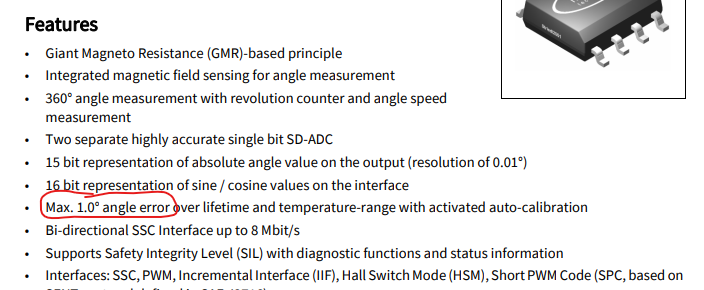
From the datasheet:
[/edit]So that's 8.5 bits of precision. The extra 6.5 bits of resolution come in handy for the servo loop, but that is not precision.
-
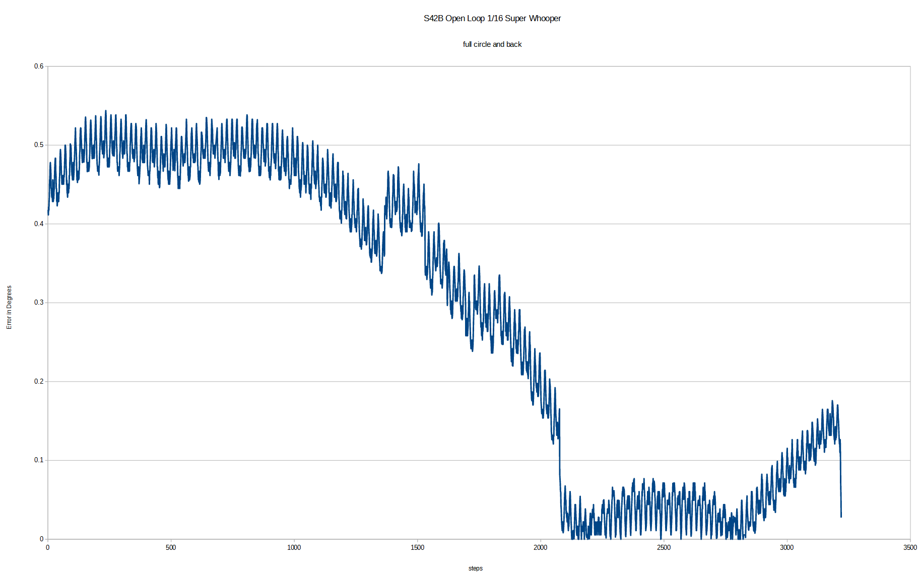
open loop, full circle, S42B

-
in closed loop mode the S42B display show constantly error between -0.04° to +0.04°
closed loop is running "much" colder than open loop and I doubt it's using full current I configured it to use (can't dig out my current probe to test, no way to get to it now)
-
The closed-loop mode of the S42B is not intended to improve accuracy compared to open-loop mode when the motor load is well below the motor's load limit.
It's intended to improve accuracy when the load intermittently exceeds the maximum motor load.
Try your open-loop vs. closed-loop experiment and hold the rotor with something for 10 steps and see how the closed-loop corrects for that once you remove the load and the open loop mode does not correct the error.
THAT'S what the closed-loop mode is for. It might cost you some accuracy in the step-to-step positioning, but you gain the ability to (when the load is lessened) correct for overload conditions and missed-steps.
Open-loop cannot do that.