Height Map - 500mmx500mmx4mm aluminium build plate
-
I guess that the ded is to heavy. It bends over its own weight. You need a thicker sheet of metal.
I had the same problem with my corexy, the simulation showed that I needed a 6mm plate with 420x420. -
@Veti yeah I think you're spot on there.
I can see the light of the BLT shining through, around the middle, and the front third of the bed.
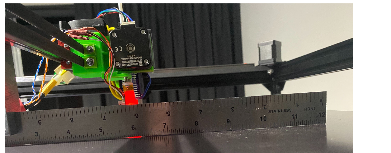
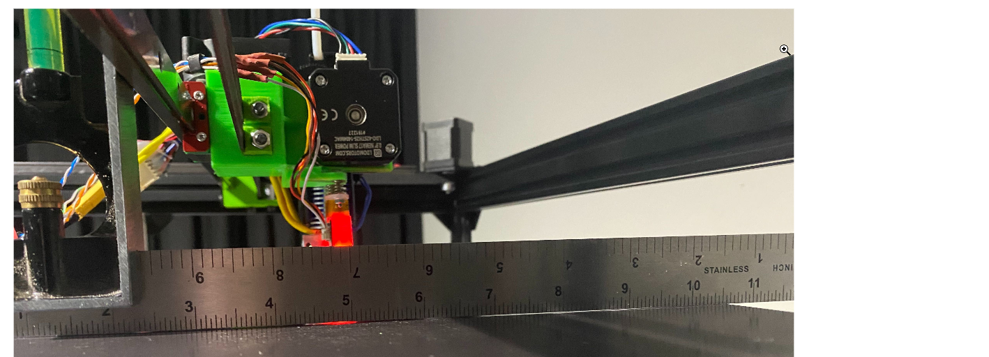
-
@vistalert said in Height Map - 500mmx500mmx4mm aluminium build plate:
I asked someone here in Perth who supplies aluminium sheet what they could offer but they said their sheet comes from a roll. So that's a none starter.
these guys? https://cncroutersaustralia.com.au/cutting-service/cnc-aluminium-cutting-and-routing-service-perth/
-
I got the simulation from a German company:
Here a 500x500 plate with 5mm so it bends on it's own weight by 0,06969mm:

And here with extra 500g: (0,7985 mm)

So they recommended to use at least a 6mm plate and I think that they are right.
Cheers, Chriss
-
@Chriss any chance you can run that with 4mm for me?
Clearly it's an issue having such a big plate, only 4mm thick.
I have an idea that I'm trying out. I have a piece of square aluminium profile I can put under and across the middle of the bed, being careful not to sit on the wires for the bed, or thermistor.
I have to do some more tests tomorrow. Tonight I was just making sure I could reset the BL Touch Z offset, do a G32, and G29 to completion. I'll see what the results are like tomorrow.
This might just add enough support to prevent sagging, but I have to carefully balance the pressure on the corner levelling bolts/springs so as to not make it bow in the opposite direction or permanently bend the plate. Worth a shot though I think.
Many thanks for this post @Chriss it's good to have some supporting data.
-
@vistalert said in Height Map - 500mmx500mmx4mm aluminium build plate:
any chance you can run that with 4mm for me?
No need.
It will be a linear elastic analysis (you're not working the plate hard enough to worry about any plasticity) so the deflection will be proportional to applied load per unit area, and inversely proportional to the section modulus per unit width. Section modulus per unit width is proprtional to thickness cubed.
So an analysis for 5mm plate can be turned into an analysis for 4mm plate by multiplying by 4/5 to account for the self weight changing, and dividing by (4/5)^3 to account for the section modulus changing. (Note that the 5mm to 4mm change basically halves the stiffness of the plate - (4/5)^3 = 0.512)
Thus, a 0.06969mm deflection due to self weight for a 5mm plate would become a 0.10889mm deflection for a 4mm plate.
The additional 0.01016mm deflection due to additional 500g would just get the stiffness ratio modification (assuming you're still planning on adding 500g) so becomes 0.01984mm, giving a total of 0.08953 (c.f. 0.07985).
As a (really very rough) approximation, deflection remaining under half thickness ought to keep you in the elastic regime, so this is still valid.
HOWEVER, I have some pretty big quibbles with that analysis. I think what has been analysed is not appropriate to your case.
The contour key is illegible, but assuming that it runs to zero at the dark blue, it's clear that there are very large flat areas at the corners. This is not a plate resting on supports at the corners - it's clamped by something very stiff (in the analysis, probably infinitely stiff) across a relatively large part at each corner. So instead of a single sagging curve, you've got a reversing curve profile - the plate is hogging at the corners, then sagging through the middle of the span. This will result in much less deflection than a case where it's actually just resting at the corners (or clamped with something not very flexurally stiff - like a single smallish bolt).
If you look at your probed heightmap, you've got a shape with sharp pinnacles at each corner. This analysis doesn't have that - it has round-topped rolling crest, with a large, flat, (uniform blue) expanse.
I've done a an analysis of a 500x500 4mm thick plate from 5083 alu (actually, just from iostropic uniform material E=72GPa, poisson=0.33, which is pretty close to 5083 alu).
Alu is 2700 kg/m3, which is 27 kN/m3. Therefore 4mm thickness is 0.108 kN/m2 or 0.108kPa.I get 0.401mm centre defelection, which is not far off your height map result.
If I generate a contour plot, with contours on the deformed shape, deflections being multiplied 700 times, I get something visually really not at all dissimilar from your height map:
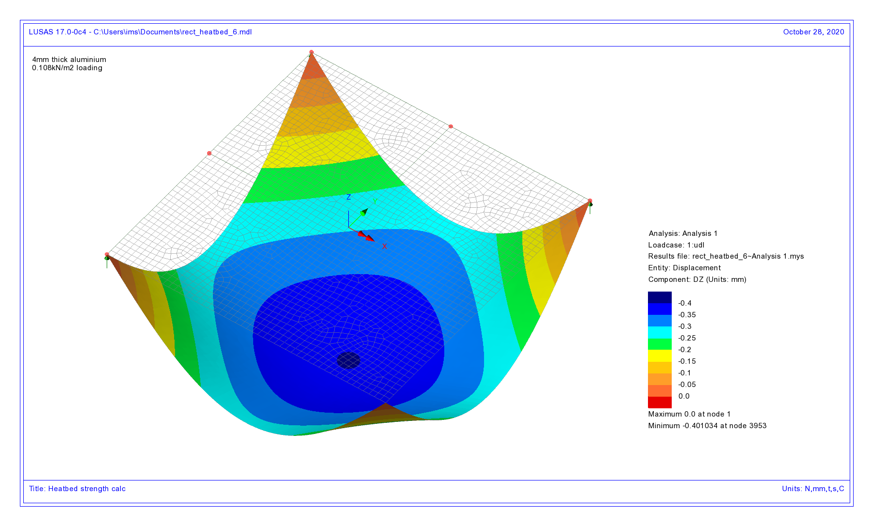
A 6mm plate will be 3.4 times stiffer than the 4mm plate, will have 50% more load, but the combined effect will be under half the self weight deflection (all other things being equal), and the deflection under a given imposed load will be under a third (1/3.4).
I'd go for at least 6mm plate. Actually, my 300mm diameter delta bed (supported at 3 points) is 6mm plate.
-
@achrn said in Height Map - 500mmx500mmx4mm aluminium build plate:
giving a total of 0.08953 (c.f. 0.07985).
Sorry, should be total of 0.12878 (i.e. 0.10889+0.01984) cf 0.07985.
-
I'll close out on this discussion, and thank everybody for the detailed input.
I've now got a 6mm glass plate so have been able to move on. Will start a new thread.
-
@achrn I can only say wow, and express my gratitude for the level of detail here. Much of it is immediately understandable to an amateur, as you describe the process, and facts needed to get to the results.
My aluminium play is indeed suspended on 4 springs/bolts at the corners. However, remember it also has a heater pad (~500x500) stuck to the back of it.
When I put a straight edge on the plate, I actually see "ripples" which I understand is not unusual for plate due to the rolling process.
Anyway, what is really interesting to me is that have placed a 500x500x6mm glass plate on top of the aluminium. I brought the plate up to 60, 70, then 80 degrees waiting around ten minutes each time to ensure the glass had time to come up to temperature too.
I was surprised by what I saw, which was the glass actually rocked around on the plate. I could get feeler gauges under almost the entire left side, which further indicated that glass is sat on a "hump" in the middle of the plate. So clearly this 4mm plate is pretty unfit for any purpose regarding a build plate.
Give your simulations and my observations, the plate appears to have issues arising from manufacturing process, and then deformations mostly due to self-weight then.
Thanks again, I learned a great deal from your response.
-
Have you considered getting a flat aluminum plate, specifically cast tooling plate, that comes milled flat? It is more likely to contact the glass everywhere and provide a uniform temperature over the surface of the glass.
-
@vistalert said in Height Map - 500mmx500mmx4mm aluminium build plate:
@achrn I can only say wow, and express my gratitude for the level of detail here. Much of it is immediately understandable to an amateur, as you describe the process, and facts needed to get to the results.
No problem - part of my living is made is explaining these sort of matters to barristers (and potentially judges) so lots of practice trying to make them intelligible. Also, I have the tools that make analyising a flat plate trivial. Normally I don't get to play with them myself - someone working for me does it. It does me no harm to prove to myself that I can still work the tools (even if only on a trivial case)!
-
@achrn very interesting. I'm working on a platform in Australia and New Zealand for online dispute resolution. 3D printing is for my hobby / personal projects. The whole ADR space is very exciting at the moment.
@mrehorstdmd I have considered that. It seems hard to source in Australia. I tried one supplier in Perth, but they told me their plate came off of a role, not cast. I will look into it, but it seems less critical if all it is doing is supporting the glass.
I'm not likely to ever take the glass off (unless it breaks) so that's why I was wondering if bonding the aluminium to the glass is a sensible idea. I put the glass on my granite worktop, apply whatever adhesive is appropriate, lay the aluminium on top and then load it up with bricks to hold it down. Is that a crazy idea?
-
@vistalert said in Height Map - 500mmx500mmx4mm aluminium build plate:
I'm not likely to ever take the glass off (unless it breaks) so that's why I was wondering if bonding the aluminium to the glass is a sensible idea. I put the glass on my granite worktop, apply whatever adhesive is appropriate, lay the aluminium on top and then load it up with bricks to hold it down. Is that a crazy idea?
It's the 'unless it breaks' that I'd be nervous of - I've cracked glass plate taking PETG off it. I'd be nervous of having bonded-on glass in case it happens again. (Of course, if you never make a mistake with your bonding / debonding layer, that won't happen - but I didn't think it would happen to me).
-
@achrn - Yes it seems "these things" have a higher incidence rate for some of us
 The conundrum is having a 6mm piece of glass, then the 500x500mm build area dictating a 7mm thick plate. That would give me a lot of mass to heat up. I do have a mains powered bed heater though.
 -
Well one thing I hate about forums is when you see these big problems discussed, and advice and solutions offered, but then there's an abrupt stop in the conversation, and you never know what happened.
Several weeks ago, as you may have read here, I was really struggling with my supplied build plate, as it's 500x500 and only 4mm thick. Also, I struggled to find anybody in Western Australia, that could supply an aluminium plate that was guaranteed to be "flat", and when I enquired in Sydney, there were limited options for tool plate.
Long story short, thanks to the collective experience of everybody in this forum, I learned how I should go out and source a new plate, or at least, work with the constrains arising due to my location, and get a plate produced.
I found an engineering company here in Perth that could start with a 10mm plate, and machine it. Their advice was it would have to be machined on both sides, because of surface tension. Turns out, to get the plate "flat" it had to be machined 5 times. The resulting thickness was 7.7mm, which thanks to the advice above I know would mean there is minimum sag, due to own weight.
So I got the plate installed, and added my 6mm glass plate and finally got by bed mesh done.
I think it's safe to say the result is amazing.
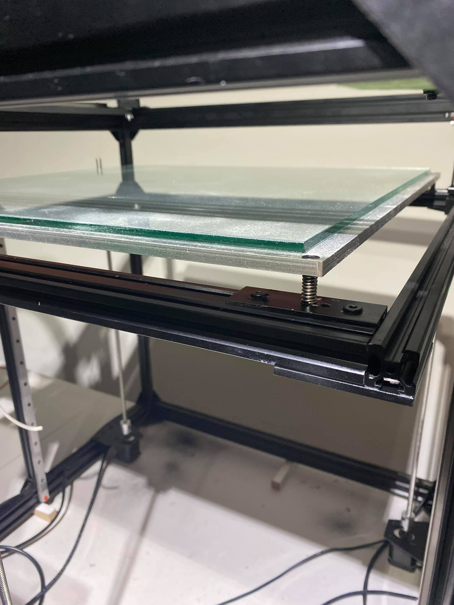
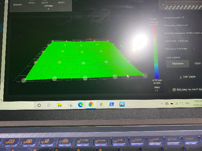
I have a few more things todo before I can actually print, but I have my "shutdown" and "startup sequence", which puts me in a great place with consistent bed mesh results.
- I have mechanical endstops for X and Y, so my homing here is pretty accurate
- I use stalling on my Z axis, and send the plate to max-z until it touches the couplings. And I call this my "parked" position"
- I now have a macros that raises the bed 480mm from the parked position, then I home all. So X then Y then Z all home.
- When I execute G29 now, I get an amazing height map.
Now I have to say the bed has been an investment, but clearly a worthwhile one. The plate cost me $280 AUD. The glass was about $25.
I've been cautioned about my bolt mountings, where the plate rests on the springs/bolts. The concern being, will the aluminium expand when heated (of course it will, by about 0.7mm), so the question comes will the plate be able to expand with these bolts in place without being completely constrained, therefore warping. Some thoughts on this would be useful.
Largely though, my issues seem to all be resolved.
-
This post is deleted!