M566 Jerk / Inst. Speed change vs time of application
-
When searching for M566 etc I get over 50 pages on hits. And as my question is rather fundamental I thought to ask in a separate thread.
I'm trying to get an idea of the forces acting on the 3D Printer during operation. One important and relatively simple move is the instantaneous speed change setting (M566). So if we go really basic we could write:
F * deltaT = m * deltaV
where:
F is the force acting on belts from Printhead / Gantry
deltaT is the time the force is acting to make the speed change
m is the mass of the Printhead / Gantry
deltaV is the velocity change.So m and deltaV are known from the printer and M566 setting. So what is F and deltaT?
I guess this is a question for @dc42 as it goes into the code but I'm assuming:
-
There is a pulse train (step/dir) running to the stepper. As an example with a frequency of 10kHz at a certain moment with a constant speed of the printhead.
-
Then all of a sudden the next line arrives and the new frequency (of step/dir) becomes 8kHz.
-
Assume this change in frequency is permissible with the M566 setting as the actual speed change indeed relates to a step/dir frequency change that falls within 2kHz speed change in this case.
Then I wonder if indeed the change in frequency is from one pulse to the other or if there is still a (very short) interval where the frequency transitions from 10 to 8kHz.
If not: then deltaT is only ±0,1msec in this case (and speed dependant)
If yes; then deltaT is roughly the frequency transition time.With DeltaT I'd have F what I'm after.
Personally I think it'll still make sense to have a transition time btw. even if ever so slow as it would limit the jerk severity a bit when moving faster and faster.
Hope my question can be answered, thanks a lot!
Q
-
-
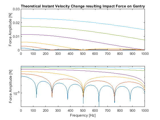
Just to feed the discussion I've computed for my CoreXY printer the amount of force that could excite the printer due to the instant velocity change with a Gantry mass of about 2.2kG . Highest level is 40mm/s change and lowest only 2.5mm/s change.

This is quite theoretical as there is a mechanical system in-between and the stepper itself, so in reality it'll be a bit different yet. In all cases the forces results in lower torque requirement than a typical NEMA17 delivers though.
So still very curious if the pulse train (Step Dir) indeed changes "instantaneous" from one pulse to the other before I continue to dive deeper in this subject. THX
-
@QuintBrand Interesting question! I don't know what the implications are with the step timing, so you'll need someone more clever to answer that. However, there are a few other things to consider.
- Fundamentally, there will be some delay between the step signals on the driver to the current rise in the motor coils, then again for it to convert that into a torque on the shaft
- stiffness of the motor. A stepper motor will typically have some position lag/error under load. This is typically small (only a fraction of a step), but will take an amount of time to build and stabilise under a step response input
- stiffness of the belt system. Even though the belts we use have steel cores, they are still a bit stretchy (plus any flex in the mounts). They are also quite highly damped (because rubber) so again there is some delay and smoothing effect from motor to print head.
- backlash in the belts, pulleys, mounts, linear bearings/rails etc will cause some non-linear effect the motion
With all of this, you will likely get quite different answers for the forces/response depending on where in the system you measure.
In reality, the motion of a printer is a very complex multi body, multi physics system so it will be quite hard to accurately compute/predict. General principle is usually to calculate the loads under acceleration, not jerk, and have some overhead for safety. Usually it's things like the bearings, backlash, getting acceptable print quality etc that dominate over system capability.