Robotic kinematics
-
@tony73 I think I have understood M208 now after analyzing the firmware. The values are the axis values, not coordinates.
So M208 will have X, Y, Z, U, V values for the 5 axes and an optinal W value for a rail. Parameter A is not necessary any more then, I changed the source and documentation.I've made a little try with Openscad to illustrate axis5offset in the documentation.
-
good morning! I reloaded the changes but as usual I don't understand how and where to put M208! I did some tests with M208 but I can no longer move the motors of the duet 3 only homing! have you tried with your robot to move it with these new parameters? my config.g was like this before
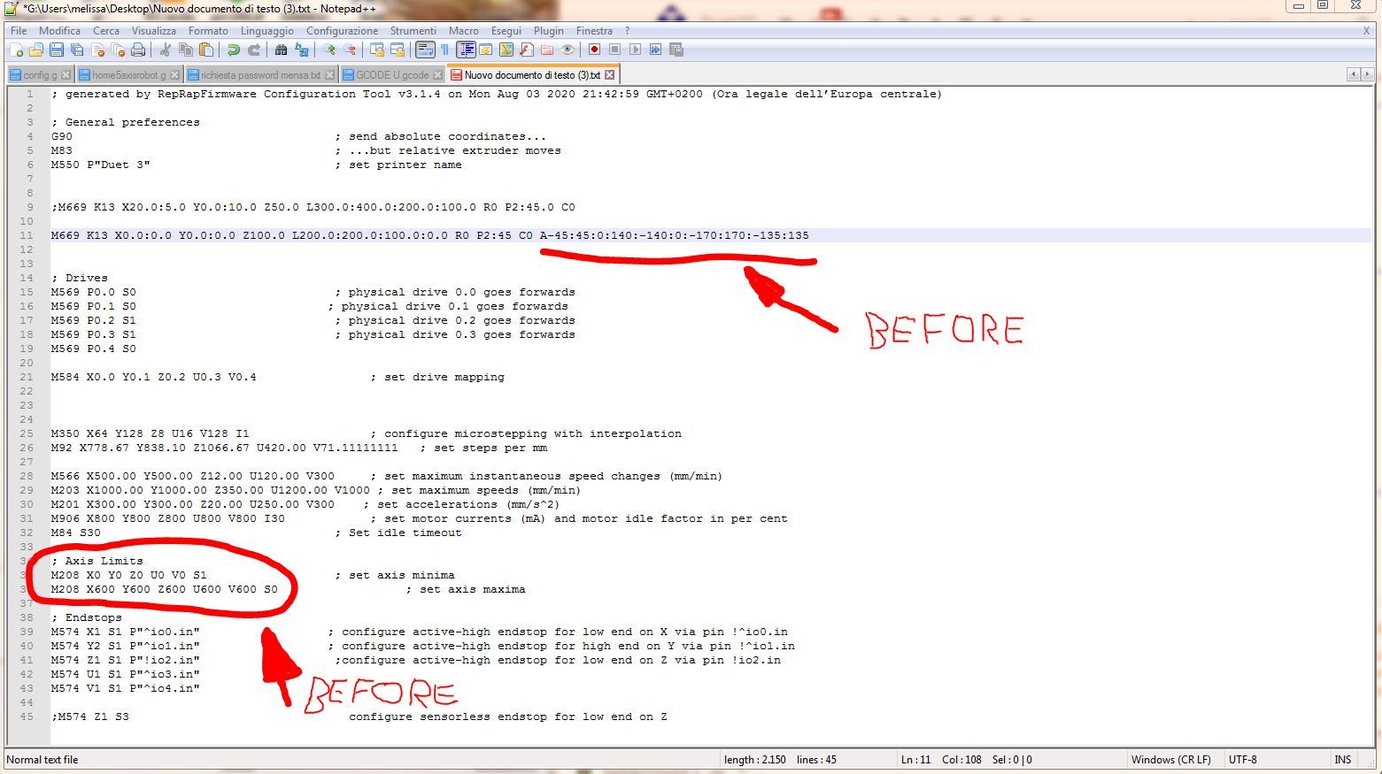
now I tried like this
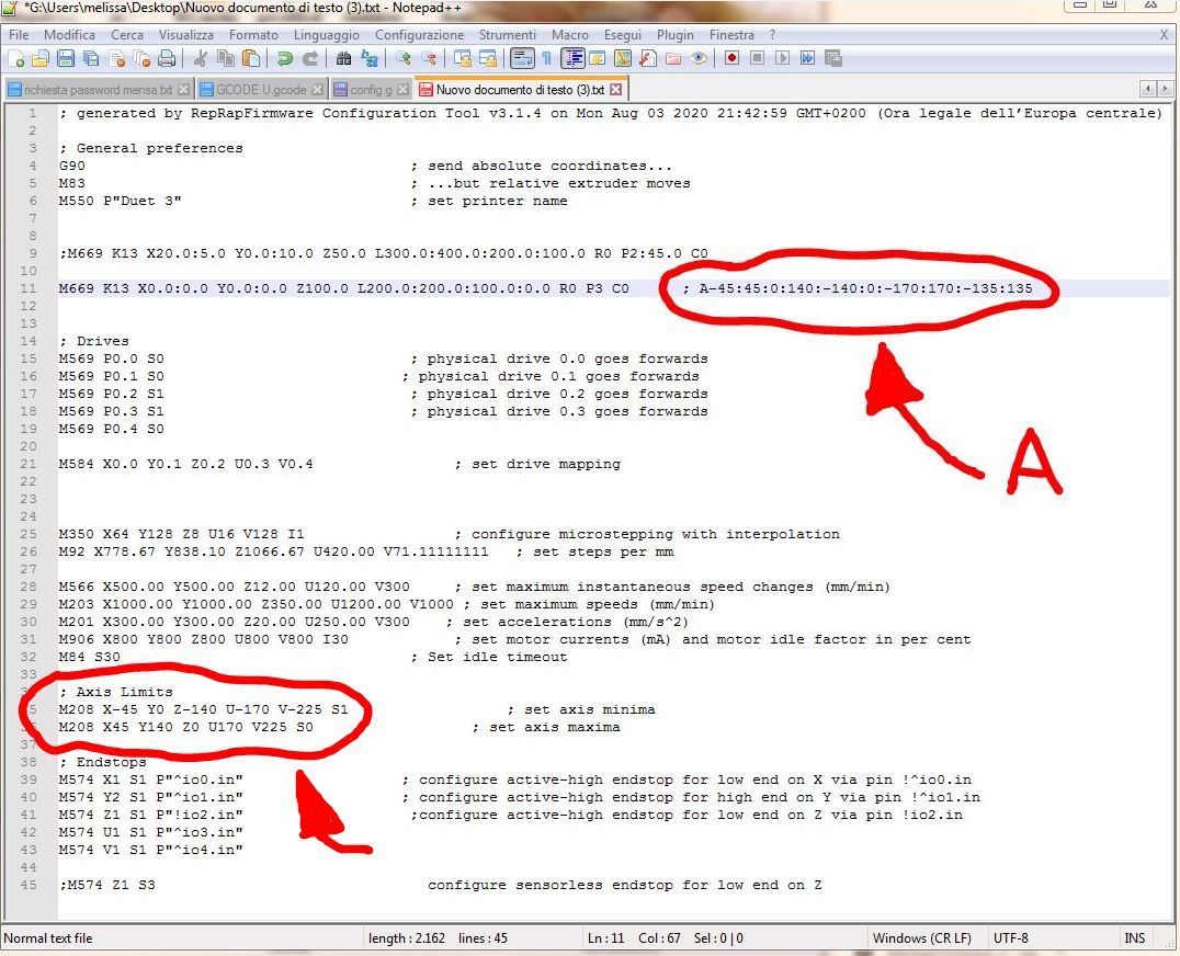
but that's not good! maybe it goes in M669 but how? but most importantly, are you trying the changes with the robot connected and moving? I ask you this to understand what I need to change!
-
@tony73 I'll check it tomorrow and tell you the result.
There is probably a bug in the code, your config is how it is meant.=> I found the bug, I'll correct and test it tomorrow.
-
I found that the motors move but it seems that the G1 commands are no longer Cartesian X Y movements but in degrees! if you send G1 X100 it does nothing but with G1 X30 it moves, like G1 Y55 moves. it moves on X Y Z U V but using the limits of degrees of M208 which are these
M208 X-45.0:45.0 Y0.0:140.0 Z-140.0:-0.0 U-170.0:170.0 V-225.0:225.0
-
@tony73 thanks a lot for the test, I've found the reason. I'll correct it and tell you when checked in.
The movements are not degrees, but for calculating the m208 restriction the original code is used (cartesian printer), this is wrong. -
@tony73 I've corrected the M208 problem and checked in the code.
-
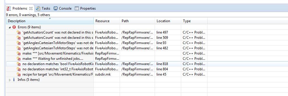
I tried to reload the code in eclipse it gives me errors, but it could be me that I am doing something wrong!
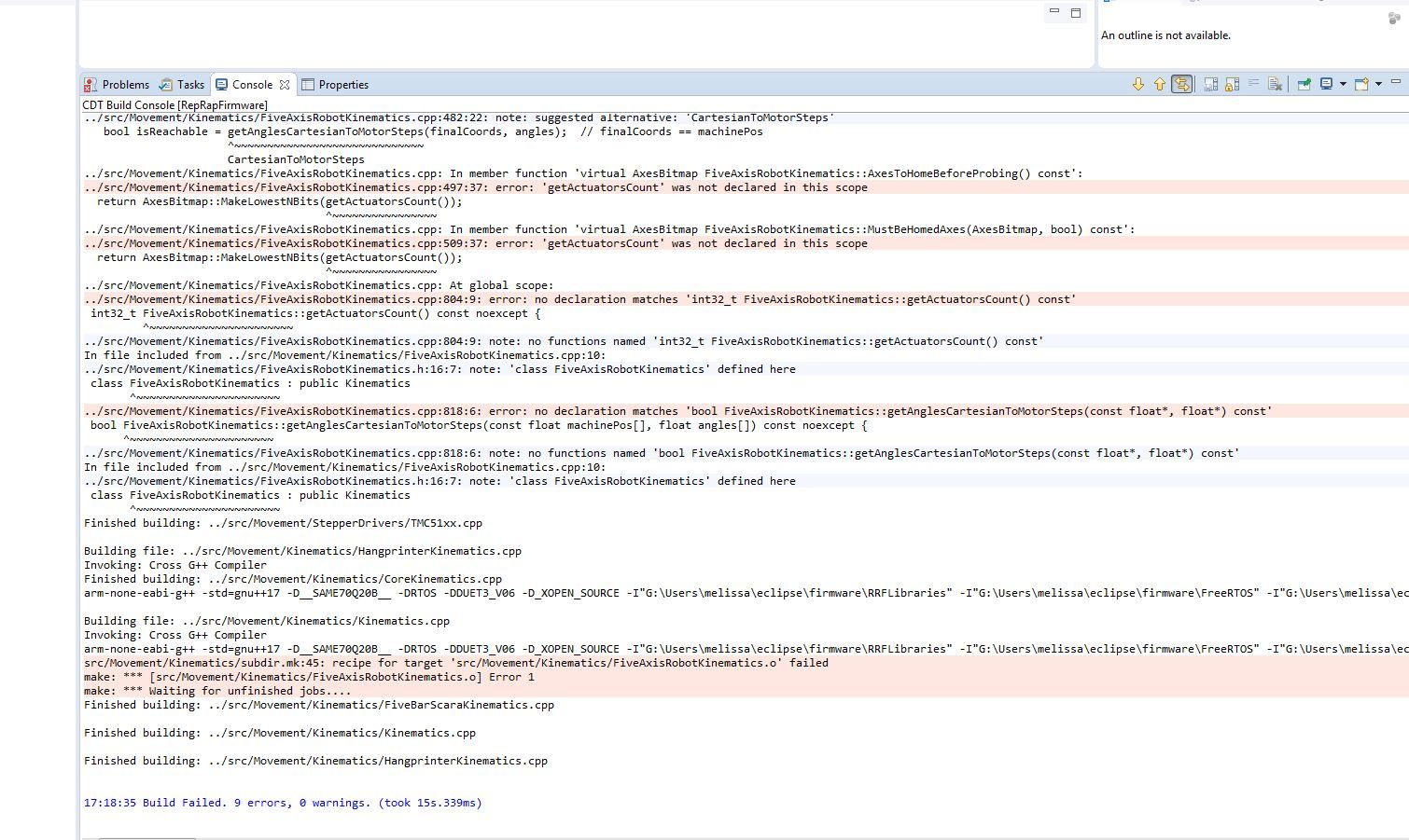
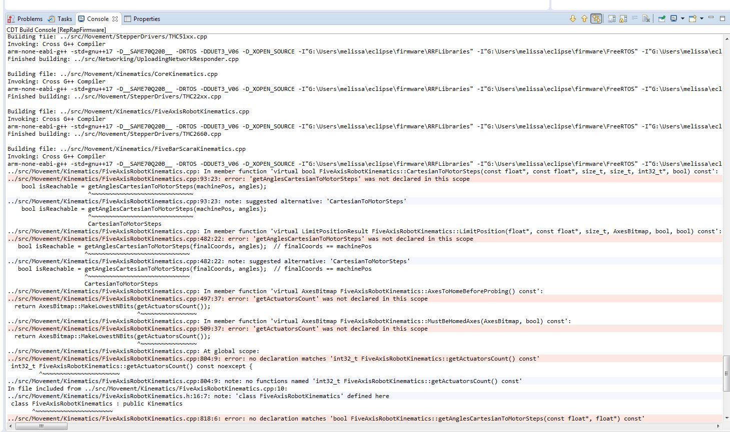
-
@tony73 grrr always this .h file....
I'll write me a postit to the display: "checkin both"!
Please try again.
-
i reloaded the firmware with the latest change in eclipse,
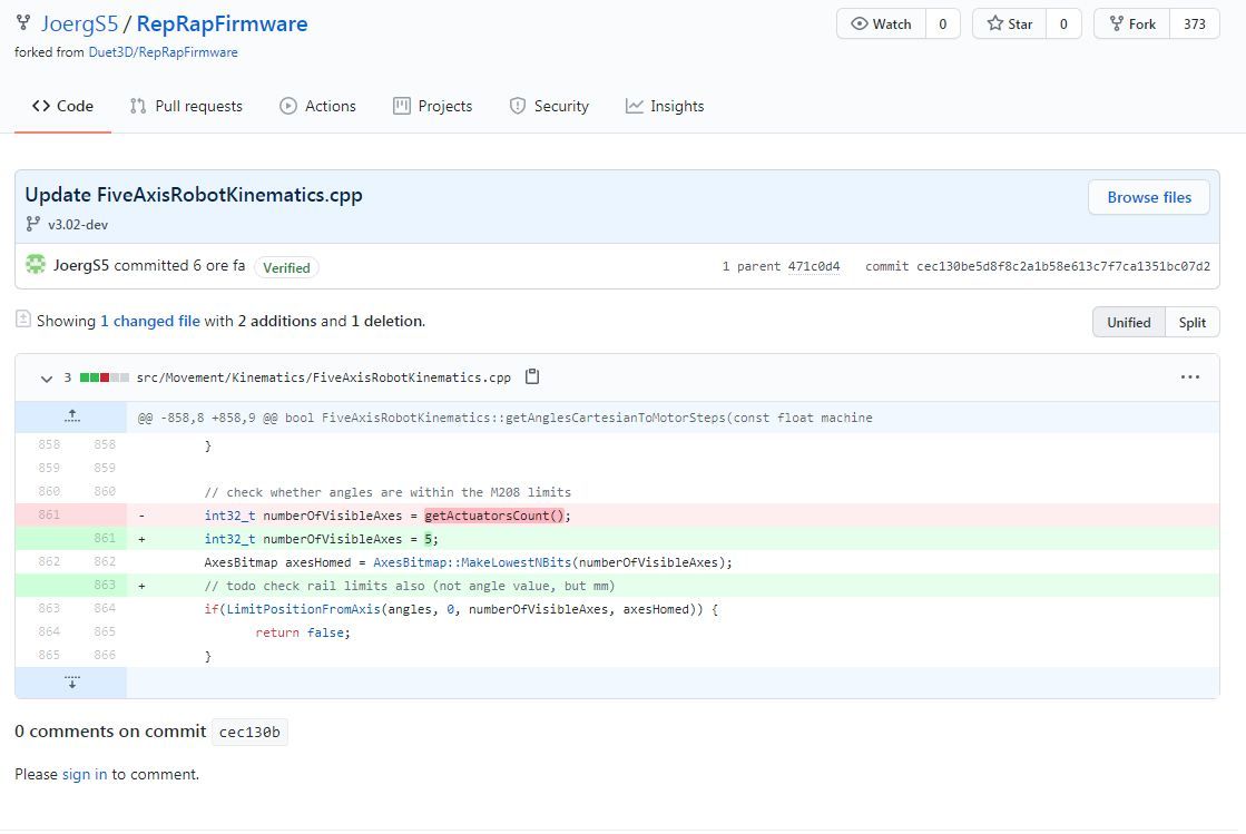
i left all parameters M669 as when i used A-45: 45: 0: 140: -140: 0: -170: 170: -135: 135 now i use M208 only change that o put P3 I was curious to see. I do everything as before homing G28 I write in simplify 3d G1 X300 but he replies that G1 / G2 / G3 are not enough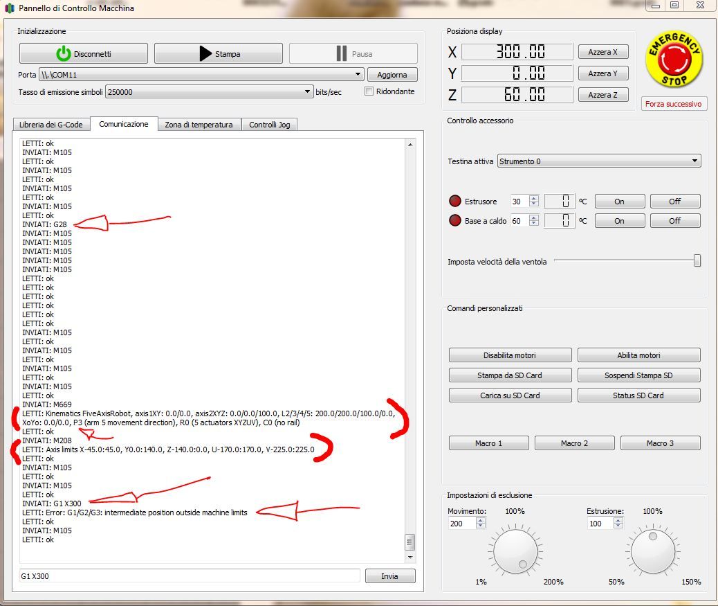
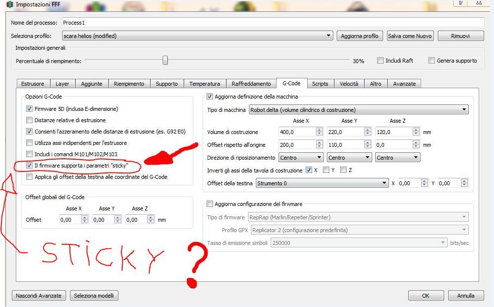
but I discovered that if I leave this parameter called STICKY active in simplify and start a print, the motors move, I stop the print, and it allows me to move the motors with G1 or G2 or G3 both in XY and Z, if I remove the STICKY parameter from simplify 3d, I start printing, nothing moves, all engines are stopped! maybe I set something wrong I don't know!
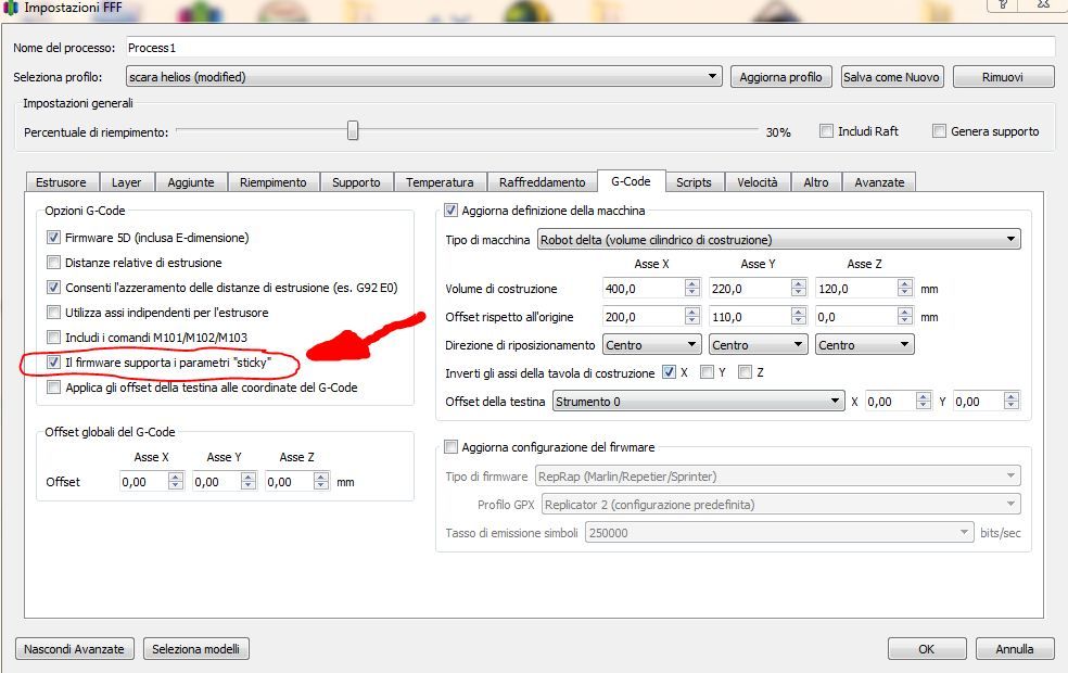
when I simulate the print with the STICKY parameter the motors move, first they make bad noises for about 5 seconds then they normalize !!
I also tried with P2: 45
same results !
-
@tony73 first idea is that your arm 5 length is 0, and I never tested it with length 0, so maybe there is an error in the code. I'll check tomorrow. (my assumption was that the hotend is never below arm 4 and must have a lenght).
G1 X300 should be reachable with arm 2 and 3 lengths of 200 each.
I'll try to extend the error message in the code, so it is more clear why firmware thinks that G1 is outside the machine limits.
I don't know sticky, what does it mean?
Could you please show your homing file, so I know what your axis values are after homing? Maybe an angle is wrong.*)
One more to check is where you are when you start the g1 x300 and whether its in absolute or relative move mode. Try a small move like g1 x20 first.
*) Please check the current positions with M114 and use absolute or relative mode G90 and G91 before the G1. (G91 G1 X20)
Your first screenshot about the source: actuator number changes with modes r0 r1 r2, but the m208 limit applies to all 5 angles always, thats why the change.
-
the sticky parameter is a 3d simplify function, I don't know exactly what it is used for.I just noticed that when it is active it can start the print and once stopped with stop it is possible to move the motors with G1 commands or with the jog control of simplify 3d, without the sticky function the print does not start and the gcode scrolls towards the end and it is not possible to move the motors.
after homing I send M114 and it replies:
X 500 Y0 Z100 U0 V5.005 I don't understand why (V 5.005) V always marks this value even if you change the arm lengths or other parameters, maybe it's a simplify 3d problem that doesn't handle V axis well !!could it be like you said arm 5 is zero long?
this and homeall
M913 X50 Y50 Z50 U50 V50 ;RIDUZIONE CORRENTE MOTORE PER HOMING
; casa x
G91 ;movimento relativo
G1 H1 X-200 F800
G1 H2 X10
G1 H1 X-20 F300; casa y
;G91 movimento relativo
G1 H1 Y-200 F800
G1 H2 Y10
G1 H1 Y-20 F300; casa z
; G1 H2 Z2 F3000
G1 H1 Z-200 F2000;casa U
;G91; movimento relativo
G1 H1 U-40 F1000
G1 H2 U15 F800
G1 H1 U-10 F500;casa V
;G91; movimento relativo
G1 H1 V-40 F1000
G1 H2 V15 F800
G1 H1 V-10 F500G90 ;torna alla modalità assoluta
M913 X100 Y100 Z100 U100 V100 ;RIPRISTINO CORENTE MOTORE FINE HOMING
however I think that now I would need a prototype of a robot arm, because with the duet 3 connected only to motors, it is not much use !!
-
@tony73 said in Robotic kinematics:
G1 H1 X-200 F800
G1 H2 X10
G1 H1 X-20 F300G1 H1 sets the position to the M208 mininum position when the endstop is hit, and for the other axes too. When you start with a G1 then, one or more of the 5 axes will try to rotate into a direction where it is beyond the limit.
What you need to do is after hitting the endstops, move all axes back to some middle positions between the angle limits, before starting G1. And the endstops will often not be at the minimum M208 position, so after hitting the endstop, set the position with G92.
I've started a homing document, where I describe the hole procedure: https://duet3d.dozuki.com/Wiki/Homing_for_a_FiveAxisRobot?revisionid=HEAD
I agree it is easier with a prototype.
My first version was from wood, but was too unstable. I am currently building it with aluminium, but have technical problems to bore exact 16 mm holes. I ordered the necessary drills, but this will take another 2-3 days. I didn't want to tell you the building plan until I know if the next version is stable enough. (In case you want to clone, I use aluminium 20x10x2 mm for the outer arm elements, and 100x20x2 aluminium for stiffness).
PS The M114 Z100 value is already outside of the M208 limits (Z shall be 0 or negative, arm 3 going down), this will prevent for a G1 command to execute.
PS2 the V value is axis 5 angle and depends on the P strategy. It will change if axis 1 angle is changed, so it depends on the X value also. X 500 means 360+ 140 degree, so somewhere rotated left "rotated behind". (in reality the 360 would mean displacing all the cables and filament).
PS3 my test program included arm5length==0, so it's no problem to set it to 0.
-
@JoergS5
I want to understand well! about X 500 you say it's 360 + 140 degrees! x 500 and given by M 114 after homing (x500 y0 z100 u0 v5.005) are these Cartesian coordinates or degrees? -
@tony73 M114 reports axis coordinates, i.e. in this case degrees. (I looked into the source code, GetCurrentCoordinates() in GCodes.cpp)
-
@JoergS5
before I changed M208 when using A-45: 45: 0: 140: -140: 0: -170: 170: -135: 135
the result of M114 after homing were Cartesian coordinates not degrees, right or wrong to understand? -
@tony73 I didn't change M114's code, so it was always axis/stepper/motor positions. With cartesian/CoreXY it is in mm, with scara and robot the unit is degrees. The values are axis values.
What I changed is the interpretation and meaning of M208. After analyzing the code, I saw that M208 checks against machine positions, so in the case of scara/robot, against degree values. The M208 degree interpretation matches G1 H1 setting the endstop position to the M208 min value in degree also, so all makes sense now (however H1 value itself often is not correct).
I am also confused by the mix of the XYZ values often. It was a bad design decision some years before when G-Code was defined to mix the meanings. I analyzed it a bit here: https://forum.duet3d.com/topic/17222/duet3d-3-custom-delta-printer-inconsistant-motor-problems?_=1594453426871
-
test to understand
i did G28
called M114 answer after homing X500 Y0 Z100 U0 V5.005
if I send G92 X40 what are degrees for actuator X 40 or position X 40 on the Cartesian plane?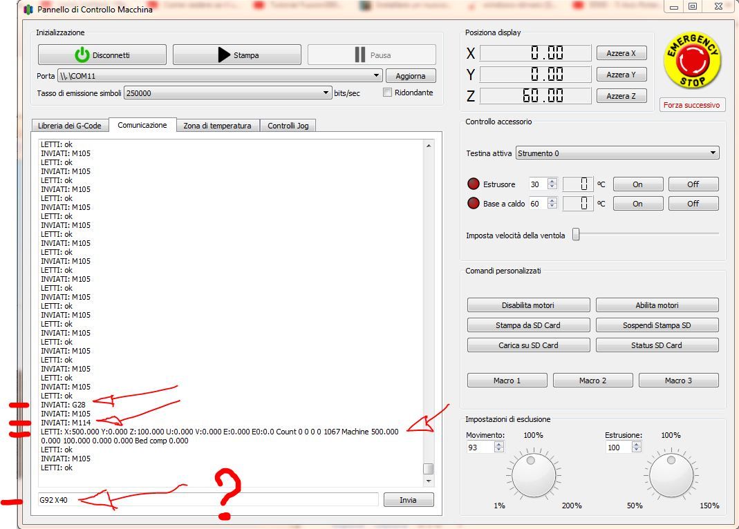
-
@tony73 according to https://duet3d.dozuki.com/Wiki/Gcode#Section_G92_Set_Position they are axis positions, ie degrees. The code is in SetPositions in GCodes3.cpp and confirms it.
When you make G92 X40 and then M114, it should show X40 as value. Testing without prototype: trigger all endstops and set the axis positions to the middle values (middle of the m208 limits) of the axes with G92. Then you should be able to move around a bit.
-
i did this test, this is M208 which i am using in config.g
M208 X-45.0: 45.0 Y0.0: 140.0 Z-140.0: 0.0 U-170.0: 170.0 V-225.0: 225.0
i did the homing G28
M114 tells me as always X500 Y0 Z100 U0 V5.005i sent G92 X0 Y70 Z-70 U0 V0
and fair as an average? or wrong?
because M114 marks X0 Y70 Z-70 U0 V0 but the motors don't move !!
I found another way to move the motors. this and M669 of config.g
M669 K13 X0.0: 0.0 Y0.0: 0.0 Z100.0 L200.0: 200.0: 100.0: 0.0 R0 P3 C0
this and M114 after homing
X500 Y0 Z100 U0 V5.005I thought that X500 was the sum L2 + L3 + L4 which would be 200 + 200 + 100, because in the instructions in the homing position the robot is stretched along the X axis
the sum of L2 + L3 + L4 is 500mm but L4 actually has to work vertically by removing L4 from 500 resulting in 400 which should be the maximum X coordinate reachable by the robot perhaps a little less than 400 example 396!
i sent after homing
G92 X390 Y0 Z100 U0 V0motors move G1/G2/G3 XYZ respond Z goes up over 200 I don't remember how much and goes down over 0 goes negative Y I don't remember how much in max and min, X is max 396 min 93,
I repeat the motors move, but not having a robot, I can't see anything else!help me to understand !
-
@tony73 you mix up X values:
M114 X is an angle. The sum of L2+L3 are coordinates,
390 is reachable because L2+L3 > 390.
The real maximum is less, because the printable area has the form of a donut: in the middle 390 is reachable, but with high or low Z it is less (arms 2 und 3 need some of their distance for the Z change).Your G92 settings look ok (but you could calculate and set the correct angle 4 to be vertical), you should start with smaller G1 movements to be sure they are in the printable area.
Angle 4 can be calculated:
angle 4 = -90 - angle2 - angle3
Your Z should not be positive (=up), but always negative. This means arm 3 goes down after arm 2 went up.The M669 Z value (= z height of axis 2) has nothing to do with the M114 Z (and G92 Z) value (axis 3 angle).