Issues with IR Probe offset
-
@agent0810 I was not aware of the other thread. If you optimized M557 already, the original value is no problem of course (because the endstop/M208 will not be at the edge of the print bed in your case, I suspect. Just be careful not to touch/damage the sensor with the brackets).
Your top layer is fiexed by brackets, so this could be the reason for the print area to be wavy. You should think about the design of the print bed according to the mrehorst blogs.
My recommendations about hair lineal was halfway serious. The idea is that with two unknowns (is the X axis uneven or the print bed?) it's difficult to know what to make better. So a hair angle (to measure perpendiculary also) is a valuable tool.
I took the best tolerance DIN 875/00. (Best would be 300 mm in your case, but they are expensive) One can measure the angle between X and Y also. -
@Phaedrux @agent0810 just a few thoughts... looking over your config.g and comparing it with mine, the probe offset should be a positive not negative, are you still using your Z end stop switch instead of the probe?
Given M29 was sending your probe to front left i would look start looking at motor direction and end stops, my ender 5 homes back right X,Y to 0,0 and my mesh always starts from here
i've added an old config of mine but its for the Duet 3 that and few other things have been changed like my X axis direction but still it might help
Regards Jim
-
@jumpedwithbothfeet said in Issues with IR Probe offset:
Given M29 was sending your probe to front left i would look start looking at motor direction and end stops, my ender 5 homes back right X,Y to 0,0 and my mesh always starts from here
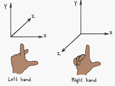
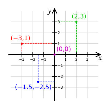
Your coordinates are reversed, but we've worked through with @agent0810 to place the 0,0 position at the front left and home to the back right to match a right hand coordinate system to match the common 3D printer arrangement. The Ender5 is an aberration in that regards. Hope that explains the difference.


-
@Phaedrux lol nope if anything you’ve just confused me more!, However don’t want to pollute this thread With my lack of understanding so I will go do some research! Either way I hope you get agent0810 printing soon I’ll be watching this thread with interest as I’ve had the same issues!
Cheers Jim
-
hey guys, sorry for the delay, got sick and was having a down system at work.
so i set it back to:
M557 X10:175 Y10:215 P8and here is what i get:
8/3/2020, 12:02:36 PM M29
GCode end-of-file being interpreted. -
-
@agent0810 just level the bed along the Y axis, this should make it better a lot.
-
i have went around multiple points on the bed and done the paper trick to get the bed as level as i think i possible can. advice on how to get it more accurate? thank you!
-
@agent0810 I meant the map shows that one side is higher than the other side in the Y direction, so you only need to make higher or lower the bed a bit on one side. I don't know what you use, screws e.g. Then the map should look a lot better and you can run the procedure again. It's often an iterative process to get a good result.
What is important, that you have a stable construction of the bed, otherwise you would have a "moving target". My second 3D printer was Prusa style, and I never finished calibrating the bed. Every time I wanted to print, it was inexact again, probably due to the springs or screws or uneven bed. It was not fun after the 10th calibration anymore, wasted time and filament.
-
It looks worse than it really is. The visual representation is exaggerated. The real differents is about 1.5mm from end to end. This could be the bed, or it could be the Y axis itself being a bit out of alignment. Do you have a flat edge ruler or machinist's square or even a builder square to check the squareness of the frame?
But you're on your way now if your probe is working.
-
@Phaedrux I’m not sure my probe is working correctly, no matter what I do it either eaves the nozzle to far from the bed (this is 85% of the time) or it is way to close and no filament comes out. Should I try moving the probe up a tad bit?
I checked the squareness of the frame when I put it together and thought it was pretty damn good.
-
@agent0810 said in Issues with IR Probe offset:
Should I try moving the probe up a tad bit?
Can you post a photo of the probe as it is mounted?
-
Of course.

-
Is that mount improved at all over the last time we looked at it?
Have you tried placing a plain white sheet of paper on the bed and testing the probe that way? Perhaps it's picking up (or not picking up, as the case may be) on the bed surface.
But your probe repeatability results look ok, at least for that single point.
-
I reprinted the mount, this was for the ender 3 but fits okay on my ender 5.
I have taped a white paper and the results were the same as without it.
What you see in the picture is as close as I can get it withought having th nozzle drag on the glass. I can use the baby steps during a print to move it but when I remove that amount in my config it makes no difference.
-
Can you perform the G30 S-1 trigger height test at multiple points across the bed? It would be good to know if the repeatability is good across the bed surface and if the trigger height changes.
What do you have in your slicer start gcode?
-
@agent0810 @Phaedrux It might be the picture but is the board to high? The quote below is from the installation instructions, worth double checking?
“The bottom edge of the board should be between 1mm and 2mm higher than the tip of the nozzle. This should give you a trigger height between 0.5mm and 1.5mm.”
Regards Jim
-
hey guys, so my buddy just put a BLtouch on his non duet board and he had to set the touch to probe before the print then save the points it pulled to get the first layer, here is the gcode he used.
do we need to do something like that?
G28 ; home all axes
G1 Z10 F600 ; raise Z axis
M190 S[bed0_temperature] ; stabilize bed
M109 S[extruder0_temperature] ; stabilize extruder
G1 X5 Y10 Z0.2 F3000 ; move to wait position
G28; Home all axes
G29; bed leveling
M500; Store bed settings
G92 E0 ; reset extrusion distance
G1 E90 F1500 ; load filament
G92 E0 ; reset extrusion distance
G1 X160 E15 F600 ; prime nozzle
G1 X180 F5000 ; quick wipe -
@agent0810 no, m500 in reprapfirmware behaves quite differently to boards with an eeprom. It only saves certain things. Check the gcode wiki entry for m500 for specifics. But in RRF as soon as g29 is run the height map is saved and applied.
-
@agent0810 @Phaedrux must be an ender 5 curse mine is also now playing up! But I have just changed out the hotend for a better one and it’s now reporting a substantial offset, if I find the issue I’ll let you know!
Regards Jim
