Weird headmap since IR-Probe
-
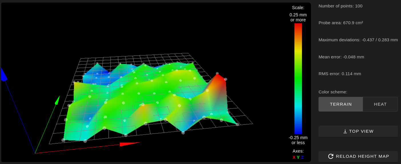
I found a pertinax (?) plate which I used for print tests some weeks ago. So I "meshed" it now for testing:


Disclaimer: Every recent test was performed on a cold bed.
-
Can you post a close up of the probe itself?
-
@Phaedrux
What do you mean? When the probe is mounted? Or do you want to the the probe itself? I can not take a picture of the front of the conductor board when it is mounted. -
Yes of the probe so we can see if anything is damaged it out of place.
Can you also test the repeatability of the probe by doing some g30 s-1 tests several times and noting the values.
-
Two new probes (for my corexy build) are on the way, I will get them later today or on Monday. I can replace the current one for testing than. And I can provide some pictures than. I guess that this makes more sense than dissembling the hotend now just for some pictures.
I tested with "G30 S-1" a bit:
G30 S-1
Stopped at height 2.400 mm
ok
G1 Z+5
ok
G30 S-1
Stopped at height 2.400 mm
ok
G1 Z+5
ok
G30 S-1
Stopped at height 2.400 mm
ok
G1 Z+5
ok
G30 S-1
Stopped at height 2.398 mm
ok
G1 Z+5
ok
G30 S-1
Stopped at height 2.400 mm
ok
G1 Z+5
ok
G30 S-1
Stopped at height 2.398 mm
ok
G1 Z+5
ok
G30 S-1
Stopped at height 2.402 mm
ok
G1 Z+5
ok
G30 S-1
Stopped at height 2.400 mm
ok
G1 Z+5
ok
G30 S-1
Stopped at height 2.398 mm
ok
G1 Z+5
ok
G30 S-1
Stopped at height 2.398 mm
ok
I used the pertinax plate for resting.... I will perform one more drill with the fr4 plate.
Cheers, Chriss
-
Here are some more test cycles with the fr4 plate. I changed nothing! Only the sheet on the bed:
G30 S-1
ok
Stopped at height 1.482 mm
ok
ok
Stopped at height 1.475 mm
ok
ok
Stopped at height 1.470 mm
ok
ok
Stopped at height 1.465 mm
ok
ok
Stopped at height 1.465 mm
ok
ok
Stopped at height 1.460 mm
ok
ok
Stopped at height 1.462 mm
ok
ok
Stopped at height 1.462 mm
ok
ok
Stopped at height 1.457 mm
ok
ok
Stopped at height 1.460 mm
ok
ok
Stopped at height 1.455 mm
ok
ok
Stopped at height 1.455 mm
ok
That seems a bit more inaccurate.
-
Ahnd here is the same test with the stock bed surface:
Stopped at height 3.740 mm ok ok Stopped at height 3.740 mm ok ok Stopped at height 3.743 mm ok ok Stopped at height 3.745 mm ok ok Stopped at height 3.735 mm ok ok Stopped at height 3.737 mm ok ok Stopped at height 3.740 mm ok ok Stopped at height 3.735 mm ok ok Stopped at height 3.733 mm ok ok Stopped at height 3.737 mm ok ok Stopped at height 3.735 mm ok ok Stopped at height 3.737 mm ok ok -
And here the results from the tests with the "PrimaCreator FlexPlate" aka "PEI":
Stopped at height 1.075 mm ok ok Stopped at height 1.077 mm ok ok Stopped at height 1.075 mm ok ok Stopped at height 1.077 mm ok ok Stopped at height 1.077 mm ok ok Stopped at height 1.075 mm ok ok Stopped at height 1.075 mm ok ok Stopped at height 1.075 mm ok ok Stopped at height 1.075 mm ok ok Stopped at height 1.075 mm ok ok Stopped at height 1.077 mm ok ok Stopped at height 1.077 mm ok -
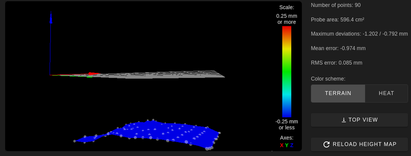
Hmmmm.... I triggered the "G29" again with the PEI sheet:

That confuses me now a bit... :?
-
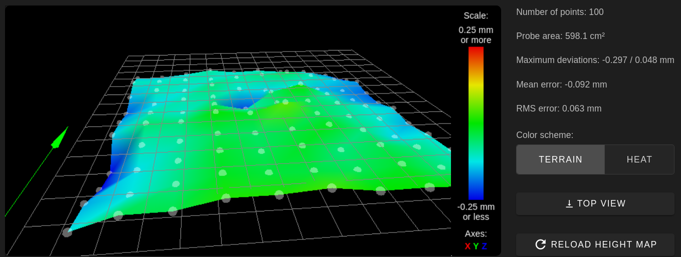
Latest picture:

I swear! There is no hole.

It is funny the hole is exactly -0.290, that is a bit to exact for me.... -
@Chriss:
I thought I would revive this thread with some useful information. I stumbled on this thread after realizing that my IR probe started giving me weird results on my FR4/G10 build sheet. (I found this interesting article that shows how IR can find voids and defects in G10, https://irinfo.org/11-01-2015-hazouri/)Based on my recent tests all at room temperature, FR4/G10 causes some issues with the IR probe. I have a spring steel build sheet with 3M 468mp adhesive topped with a .020" G10/FR4 sheet. I can confirm that I get readings from the IR probe that are not correct on clean FR4 (cleaned with 99% isopropanol and no coatings and with a lightly sanded finish on the FR4)
To confirm my suspicion, I performed mesh compensation probing, then picked 2 spots on the map showing a high next to a low. The two spots are 40mm apart in the x-direction with the IR probe measured difference of almost 0.2mm. Disabled mesh compensation (not necessary for the G30) but necessary for the dial indicator measurements) probed G30 S-1 got a reading from the IR probe of 0.005mm of what the mesh compensation point previously measured (it showed consistency in measurements of the IR probe). Then I took an analog dial indicator attached to my x extruder stepper motor and zeroed at the first point and dragged the dial indicator to the other point. The dial indicator showed a worst-case of <0.01mm difference at most between the two points. This included sweeping the area around each point with the dial indicator in case my offset on my IR probe was not perfect. This was all done with power to the stepper motors to ensure repeatable measurement points.
To further confirm, I placed one continuous piece of masking tape over the two spots and remeasured with the IR probe and the Dial indicator. With the tape in place, I measured <0.01mm difference in height between the two spots with both the dial indicator and the IR probe.
Also in regards to your plot of the PEI bed, I believe PEI is transparent to IR so you would be measuring whatever is below the PEI.
I just painted the FR4 build sheet (previously was showing a lot of height variation) with high temp paint. (I hope it sticks well when removing parts (after curing the paint)). After painting, I get the nice flat bed measurements I was expecting on my printer. If the high temp paint works for printing, I will try to post up the paint I used. I will likely ditch the FR4 and paint the spring steel sheets for my custom built mag bed. It will depend on how well the paint holds up to being printed on. At least if I paint the spring steel, I can cure the paint to a higher temp which might help it hold up to the plastic extrusion temps better.
As a side note: I use Airwolf Bed adhesion coatings on the fiberglass with really good luck with their ABS, PC and PLA coatings. I have had mixed results with the nylon coating, but it has been a really long time since I tried printing on it.
Also, I found I have to run mesh compensation mapping with the IR-Probe when the bed and chamber are cool and at a constant temperature. I found there is a ton of drift as the sensor heats up above a hot bed.