Better result with autocalibration ?
-
Hello.
I need your knowledge and experience about autocalibration on delta printer.Below are my steps of autocalibration.
Initial settings
M665 L288.6:288.6:288.6 R170 H261.6 B114.0 X0 Y0 Z0.000
M666 X0 Y0 Z0 A0 B0
1st autocalibration
G32
Calibrated 7 factors using 13 points, deviation before 0.367 after 0.010

M665 L291.540:291.540:291.540 R171.633 H261.667 B114.0 X-0.351 Y-0.271 Z0.000
M666 X0.958 Y-1.234 Z0.276 A0.00 B0.00
2nd autocalibration
G32
Calibrated 7 factors using 13 points, deviation before 0.009 after 0.009

M665 L291.684:291.684:291.684 R171.682 H261.665 B114.0 X-0.350 Y-0.278 Z0.000
M666 X0.963 Y-1.236 Z0.273 A0.00 B0.00
3rd
G32
Calibrated 7 factors using 13 points, deviation before 0.012 after 0.010

M665 L291.670:291.670:291.670 R171.679 H261.660 B114.0 X-0.337 Y-0.253 Z0.000
M666 X0.953 Y-1.229 Z0.276 A0.00 B0.00
Last one
G32
Calibrated 7 factors using 13 points, deviation before 0.010 after 0.009

M665 L291.669:291.669:291.669 R171.687 H261.659 B114.0 X-0.327 Y-0.234 Z0.000
M666 X0.933 Y-1.218 Z0.285 A0.00 B0.00
And then Mesh Compensation
21 points probed, min error -0.015, max error 0.065, mean 0.011, deviation 0.026According to me it looks good, it could be better but it should run well.
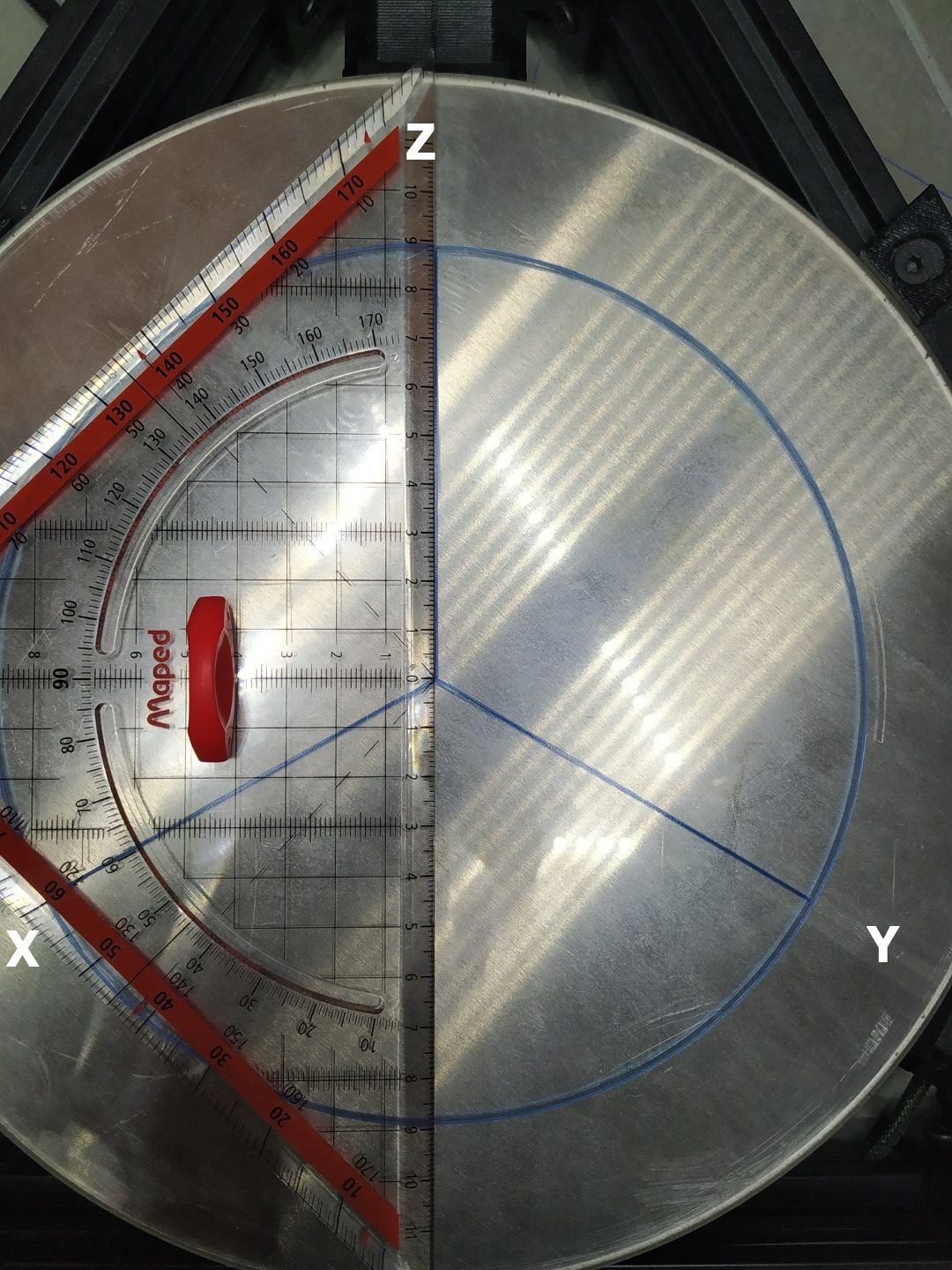
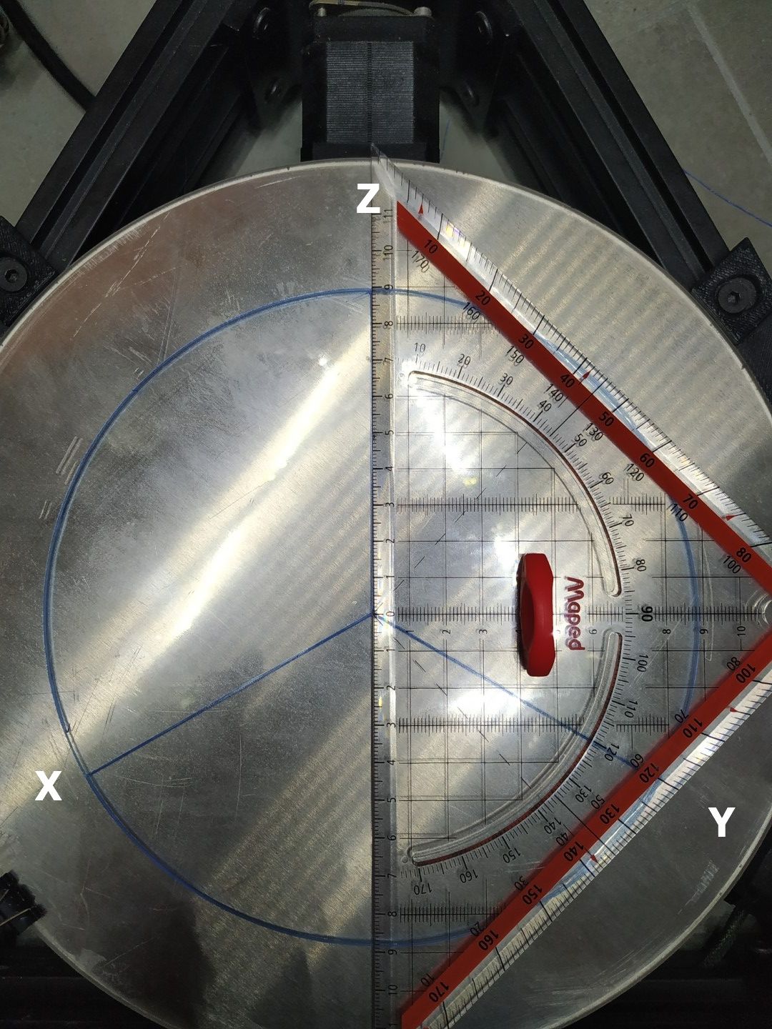
So I printed this STL file to test the angle between each tower.


I have 2 questions:
1/ What is your opinion about the result of autocalibration and mesh compensation ?
2/ If you zoom in, you can see that the angle correction is not perfect and can affect the squareness of big prints. Autocalibration seems not to be able to do better. Is there a way to have perfect correction ?Thank you.
-
Hello. I'm not a delta expert, but I do know that most issues can be solved by a careful reading and implementation of the methods described here: https://duet3d.dozuki.com/Wiki/Calibrating_a_delta_printer
-
Are your diagonal arms (rods) a known length? In particular, are they Hayden Huntley magnetic ball end arms? If you know the length, either from measuring, manufacturer doc, or Hayden's stickers, then put that length in M665 L and do not allow auto calibration to change it.
Auto cal is a wonderful thing for Deltas, I run a quick version before every print... but... it does not always adjust L correctly. Note that it changed your initial 288.6 to 291.6xx. That's 3mm, and that is a LOT.
Anyway, long winded: If you are certain about your arms, set them, and use the variations of cal that do not change them.
Then, run the experiments you've run, and post results again.
-
@Danal Yes I agree with DANAL use S6 or S8 as the autodial factors if you know the rod length accurately.
-
@Phaedrux Thank you. I know it and I did my best by following this methods many time. The main difficulties is to find what you really have to fix according the issue you face. I have checked everything many time, and for sure touching the hardware add sometime new issue.
-
@Danal Thank you for your help. Unfortunately I don't know my rods length and my caliper is too small.
They are not original Hayden Huntley ones but they are the same.
I agree with you, autocalibration is not perfect and the rod length has too much difference after each autocalibration. And I guess that the rod length is the most critical settings for good calibration.I tried to measure the rod length of each one using this method.
For each tower:- I fix my caliper on the tower. It's perpendicular to the tower.
- The end of the caliper is touching the head.
- I move the head 50 mm along the axis of the tower to the tower
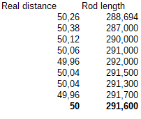
Tower Y exemple G1 X25.98 Y-15 G1 X69.282 Y-40- Then I change the setting of the rod length and measure again until the head move the right distance.
Here is an exemple for the Y tower

Not sure than this method is the best one and if it's accurate enough. But I was surprised when I read from one autocalibration quite the same result.
As you can see, printing using this settings shows that the 120° angle are wrong. 100x100 square is not really square and 100mm round piece is not really round as well.
What about manually changing M665 X,Y and Z settings ?
-
Sounds like a good technique.
You can manually change those settings... Before you do that, I'd run several S6 or S8 autcalibrates with the rod length set to 291.6, and see what you get.
-
The caliper is a issue but at least you can try this:


I was getting real mad because I can't figure out what damn problem cant make this trap print. I'm still working on it and I'll post "succes!" just at the end of this pain (enclosure, bed heat uniformity , etc etc). BUT I learned that BEFORE any software refinement the hardware MUST be more accurate much as possible.
This check is not expensive but can help a lot to find macro "crap".
If you will feel play trying moving the bar , they are not equal... -
Hello. Sorry for my silence.
I have broken my glass bed. Waiting for the new one to do new tests.
And the new one will be this bed https://flex3drive.com/product/printbite/?attribute_size=Ø+250mm&attribute_colour=Clear&attribute_graphic=Plain&attribute_texture=Matt