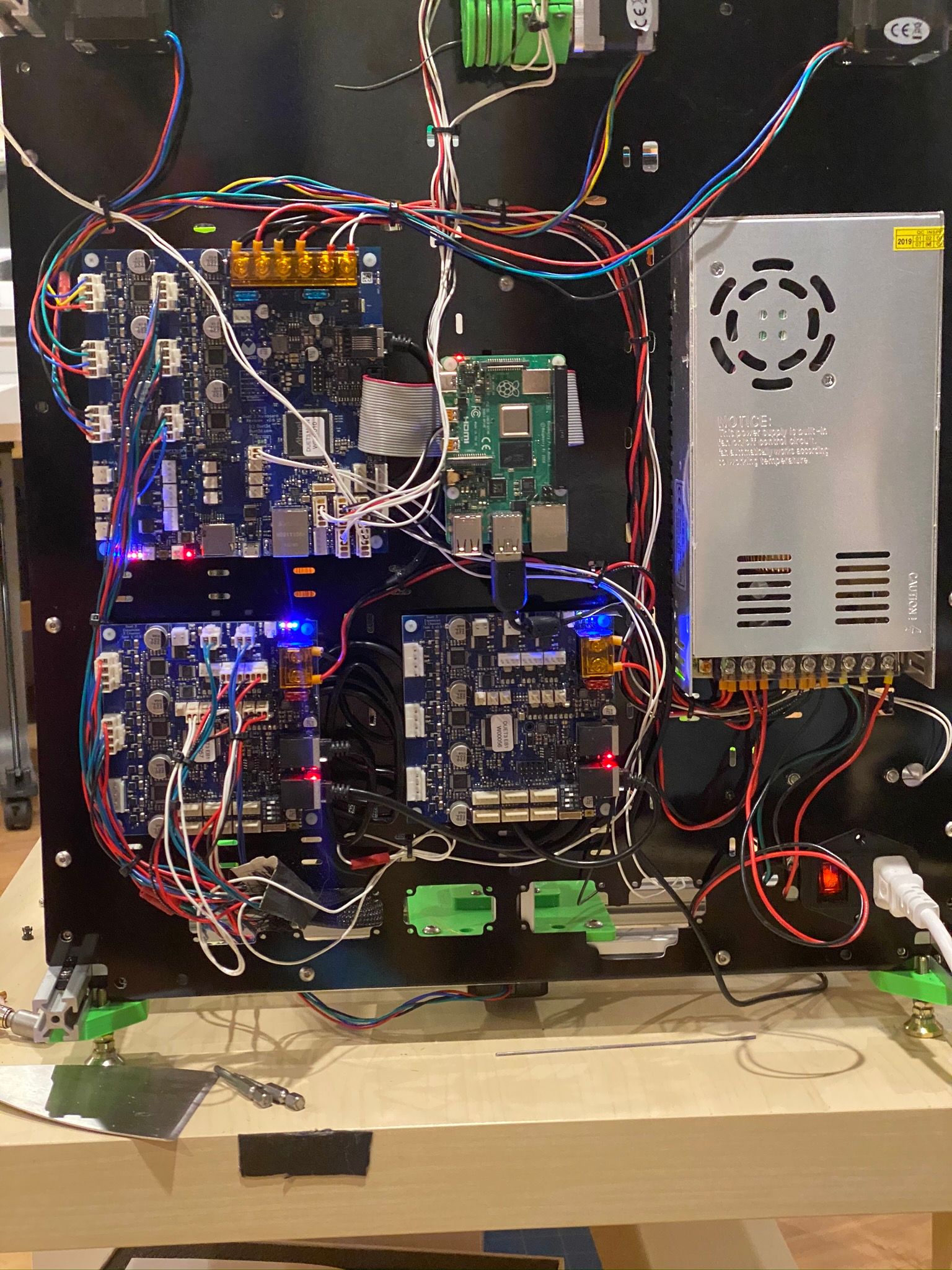
Duet3 6Hc + Duex 3Hc with Raspberry 3B+ Wiring Check
-
Hi,
Due to the circumstances my Duet3 6hc 1.0 + Duex 3HC + Rasp. 3b+ Printer was left a bit behind for a while .Does this final wiring look okay for you, or can you see any shortage which may happen if i turn it on?

*The Power Supply is 12v 360w and all its components are 12V
*The Raspberry is flashed with the Duet3 Pi iso and was booted like told in the instructions before with the Mainboard.My Hotbed does not seem to show me minus or plus poles, can this be critical for the Duet3?
The Power for the Hotbed goes in directly from the Power Supply to the second +- crimp connector and leaves over the Crimp 3 out connector into the Hotbed.On the Crimp connector Bay 1 is the Power from Power Supply and the Duex3 HC Board chain bridged.
At the Duex 3 itself is just jumper 1 turned to on from the 4 switches.Correct me if i'm wrong or please tell me if i may missed some.
Please take a look and check if you can find any critical faults so fae that i can give it a go without risking it.
Many Thanks for any advice.
-
This post is deleted! -
I have to assume you've been using this? https://duet3d.dozuki.com/Wiki/Duet_3_Mainboard_6HC_Wiring_Diagram
I'm having trouble parsing this sentence:
The Power for the Hotbed goes in directly from the Power Supply to the second +- crimp connector and leaves over the Crimp 3 out connector into the Hotbed.
But I think you're describing the correct procedure for powering the bed:
The separate OUT0 Power in allows for a different voltage to be supplied for the OUT0 high current output (e.g for a large bed heater) If this is not required VIN power must be applied to both the POWER IN and the OUT0 POWER IN terminals for OUT 0 to be powered.
(Which is also difficult to parse, I admit)
I think you've got it right, but consider doing the commissioning in a more staggered manner. Start with just the Duet3 and some heaters, fans, and motors and confirm they are working. Get the hang of the config in standalone mode. Then connect the external board, and finally, get into the Pi connection.
-
Pi + 6HC + 2x 3HC (plus tool distribution and tool boards not in this pic).
USB on the Pi goes to a camera.
Skinny wires on 3 group of screw terminals, output to bed, goes to an SSR for a 110V bed.

-
You need to set the CAN address on your expansion board. It is currently set to 0, and this will cause no end of grief.
Little switches, on a red block, upper left of 3HC in your photos. Look carefully at mine (which are lower right, and black) and set it like my first board.
-
I can't see the jumpers for you Pi power, there is a yellow cable crossing in front of them. Double check them per the wiring diagram.
-
@Danal said in Duet3 6Hc + Duex 3Hc with Raspberry 3B+ Wiring Check:
You need to set the CAN address on your expansion board. It is currently set to 0, and this will cause no end of grief.
Little switches, on a red block, upper left of 3HC in your photos. Look carefully at mine (which are lower right, and black) and set it like my first board.
Thanks, it's the same as yours. Switch number 1 is on and the other 3 are on off.
-
@Danal said in Duet3 6Hc + Duex 3Hc with Raspberry 3B+ Wiring Check:
I can't see the jumpers for you Pi power, there is a yellow cable crossing in front of them. Double check them per the wiring diagram.
INT 5 EN and 5V TO SBC are bridged so that the SBC gets the power from the Duet.
Thanks, so i will plug it in and make a Duet Pi upgrade via sudo apt-get update / upgrade from its Screen, Keyboard and Mouse which are plugged in. -
@Flex3D said in Duet3 6Hc + Duex 3Hc with Raspberry 3B+ Wiring Check:
Thanks, it's the same as yours. Switch number 1 is on and the other 3 are on off.
AHA! They sure are. They fooled me the first time I looked at the photo, even enlarged.

-
@Danal said in Duet3 6Hc + Duex 3Hc with Raspberry 3B+ Wiring Check:
@Flex3D said in Duet3 6Hc + Duex 3Hc with Raspberry 3B+ Wiring Check:
Thanks, it's the same as yours. Switch number 1 is on and the other 3 are on off.
AHA! They sure are. They fooled me the first time I looked at the photo, even enlarged.

It's no bother.
Now i'm at the cofig.g and having some wired points like my Z Probe is my z Endstop. Can i leave it even blanc or do risk a hot bed crash?; Endstops
M574 X1 S0 P"io1.in" ; configure active-low endstop for low end on X via pin io1.in
M574 Y1 S0 P"io0.in" ; configure active-low endstop for low end on Y via pin io0.in
M574 Z1 S2 ; configure Z-probe endstop for low end on Z; Z-Probe
M558 P1 C"io3.in" H5 F120 T6000 ; set Z probe type to unmodulated and the dive height + speeds
G31 P500 X0 Y0 Z2.5 ; set Z probe trigger value, offset and trigger height
M557 X15:300 Y15:300 S20 ; define mesh grid