G29 Mesh level error.
-
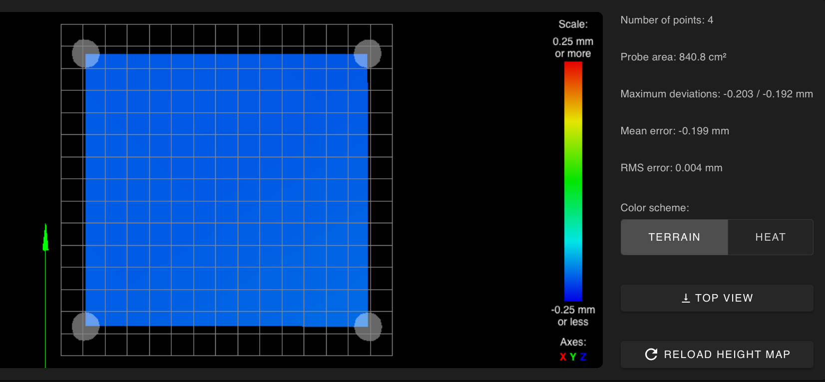
Alright I'm pulling the few hairs out of my head that I have left. Doing the mesh map, everything is nice and flat and square and I get this, the mesh hap is probing well below the surface
"G29
Warning: the height map has a substantial Z offset. Suggest use Z-probe to establish Z=0 datum, then re-probe the mesh.
4 points probed, min error -0.203, max error -0.192, mean -0.199, deviation 0.004
Height map saved to file heightmap.csv"G28 has been done and everything seems correct just the .2mm error in the Mesh Map

My Config.g is here
; Enable WiFi ; General preferences M555 P2 ; Set output to look like Marlin M575 P1 B57600 S1 ; Comms parameters for PanelDue G21 ; Work in millimeters G90 ; Send absolute coordinates... M83 ; ...but relative extruder moves ; Axis and motor configuration M584 Z5:6:7 ; Z steppers are 5 (front left) 6(rear left) 7(right) on the duex5 M667 S1 ; CoreXY mode M569 P0 S0 ; Drive 0 goes forwards (change to S0 to reverse it) M569 P1 S1 ; Drive 1 goes backwards M569 P2 S1 ; Drive 2 goes forwards M569 P3 S1 ; Drive 3 goes forwards M569 P4 S1 ; Drive 4 goes forwards M569 P5 S1 ; Drive 5 goes backwards M569 P6 S1 ; Drive 6 goes backwards M569 P7 S1 ; Drive 7 goes backwards ;Leadscrew locations M671 X-12:-12:342 Y14:277:149 S7.5 ;Front left,(-12,14) Rear Left (-12,227) , Right (342,149) S7.5 is the max correction - measure your own offsets, to the bolt for the yoke of each leadscrew 9/1 ; Axis and motor configuration M350 X16 Y16 Z16 E16 I1 ; set 16x micro-stepping for axes& extruder, with interpolation M574 X1 Y1 Z0 S0 ; set homing switch configuration (x,y at min, z at max) M906 X1750 Y1750 Z1400 E1000 I25 ; Set motor currents (mA) M566 X600 Y600 Z80 E3600 ; Set maximum instantaneous (jerk) speed changes (mm/min) JOHNCFI 7/8 M201 X1750 Y1750 Z20 E1500 ; Set accelerations (mm/s^2) JOHNCFI 7/8 M203 X12000 Y12000 Z900 E3600 ; Set maximum speeds (mm/min) JOHNCFI 7/8 M208 X295 Y285 Z330 ; set axis maxima and high homing switch positions (adjust to suit your machine) M208 X0 Y0 Z-0.5 S1 ; set axis minima and low homing switch positions (adjust to make X=0 and Y=0 the edges of the bed) M92 X160 Y160 Z3200 E830 ; steps/mm ; Thermistors M305 P0 S"Bed" T100000 B4240 R4700 H0 L0 ; Put your own H and/or L values here to set the bed thermistor ADC correction M305 M305 P1 X200 ; Put your own H and/or L values here to set the first nozzle thermistor ADC correction ;Bed heater M305 P107 S"Keenovo" X7 T100000 B3950 R4700 H0 L0 ;Heaters M307 H1 A564.3 C147 D4.2 S1.00 v24.4 B0 ; Heater 1 model M570 S360 ; Hot end may be a little slow to heat up so allow it 180 seconds M143 S385 ; Fans M106 P1 T45 S1 H1 M106 P4 S1 :M106 P0 T45 H1 ; disable thermostatic mode for fan 0 ;M106 P1 T45 H-1 ; disable thermostatic mode for fan 1 ;LEDs M106 P3 S.50 ; Set fan 3 value for our LED to on. ; Tool definitions M563 P0 D0 H1 ; Define tool 0 ;M563 P1 P0 D0 H1 ; Define tool 0 G10 P0 S0 R0 ; Set tool 0 operating and standby temperatures ; Probing configuration for Precision Piezo Orion Z-Probe ;*** WARNING: This section has not been tested throughly yet, and is based off community input. Use at your own risk. ;*** NOTE: M558 H3 and R0.5 values have been working for a year on Xepherys' self-sourced RCII300ZL. This requires fine-tuning ;*** of the Orion itself. The default values of H5 and R0.75 are "safer" options if your tuning varies. ;*** NOTE: G31 Z-value of Z0 is excellent for hard surfaces (glass, Garolite, et cetera). Softer surfaces like BuildTak ;*** may see better results with Z-0.10 ; Precision Piezo Orion v2.0(analog) M558 P1 F75 H2 I1 R.5 T6000 A5 S0.002 ; Set Z probe type to switch and the dive height + speeds G31 X0 Y0 Z-0.108 P20 ; Set Z probe trigger value, offset and trigger height ;Piezo Orion Orion v2.0(digital) ;M558 P8 F350 H5 I1 R0.2 T6000 A5 S0.002 ;maybe faster speeds ;G31 P50 X0 Y0 Z-0.108 ; 1/25/19 ;M557 X45:245 Y46:254 P2:2 ; Set Default Mesh - NOTE: take probe offset into account - corners only John OCFI 5/12 was 282 M557 X0:285 Y285:295 P2:2 ; EF 5/17 ;*** If you are using axis compensation, put the figures in the following command ;M556 S78 X0 Y0 Z0 ; Axis compensation here ;M208 S1 Z-0.2 ; set minimum Z M501 ; read from config.g G29 S1 ; Load Height map M376 H10 ;Taper Correction off 8/21 T0 -
Bed.g
;4 point bed level
M561 ; clear any existing bed transform
G1 Z5 S2
G30 P0 X0 Y0 Z-99999
G30 P1 X0 Y285 Z-99999
G30 P2 X295 Y285 Z-99999
G30 P3 X295 Y0 Z-99999 S3
G1 X0 Y0 F5000 ; move the head to the corner (optional); 3 point bed level
;M561 ; clear any existing bed transform
;G1 Z5 S2
;G30 P0 X0 Y0 Z-99999
;G30 P1 X0 Y285 Z-99999 ;Y was 295 5/12
;G30 P2 X290 Y142.5 Z-99999 S3
;G1 X0 Y0 F5000 ; move the head to the corner (optional)Homeall.g
G91 ; relative mode
G1 Z5 S2 F400
G1 S1 X-280 Y-240 F1200 ; course home X or Y
G1 S1 X-240 ; course home X
G1 S1 Y-240 ; course home Y
G1 X4 Y4 F1200 ; move away from the endstops
G1 S1 X-10 ; fine home X
G1 S1 Y-10 ; fine home Y
G91
G1 Z5 F800 S2
G90
G1 X147.5 Y142.5 F2400
G30
G1 Z5 F200
G90 ; back to absolute modeHomeZ.g
G91
G1 Z5 F800 S2
G90
G1 X147.5 Y142.5 F2400
G30
G1 Z5 F200and the Mesh Level Marco I'm running
G91
G1 Z5
;M557 X10:295 Y50:295 S30
M557 X0:290 Y0:290 S290 ;test 8/16
G29 -
@EFletcher said in G29 Mesh level error.:
G29 S1 ; Load Height map
remove that from config.g. It's loading the heightmap before you've even homed the printer, hence the warning. That may resolve the issue.
You may also want to add a single G30 at the center of the bed after you've done the leveling to reestablish the Z0 point.
What is the order of operations you're commanding things to happen?
-
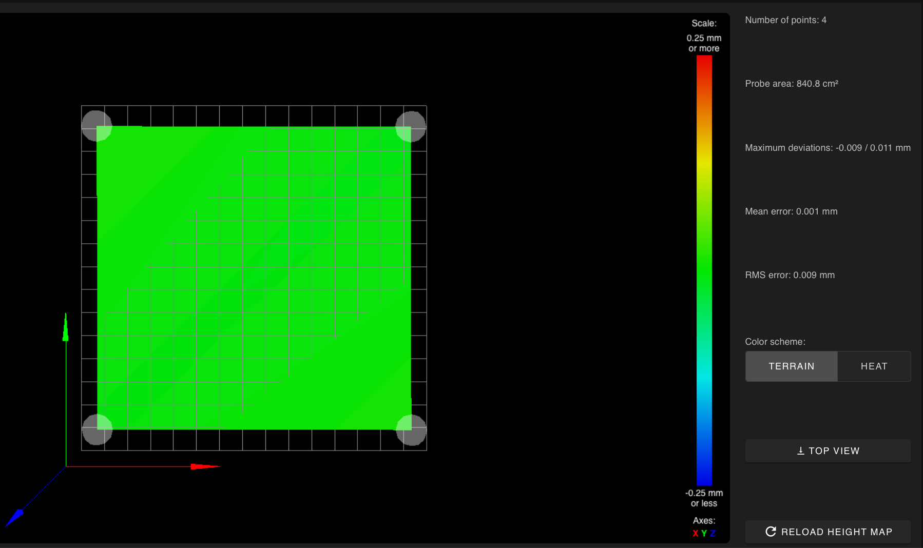
Thanks that seems to have done it
-

Amazing what happens when you don't call for things before they are needed! Thanks for the help