Mesh bed Levelling with BLTouch. Am I doing something wrong?
-
Hi all,
I've been trying to diagnose this for a long time, without success, and is creating a lot of frustration, because at this point I'm not sure if is a mechanical issue, configuration issue or any other thing.
I'm using a BLTouch (original, as per the QR code) in a 300x300 CoreXY (Hypercube Evolution+some mods), and I've also tried PINDA and DC42 IR as Probes, with same results. I'm executing a G32 and a G29 before each print, and for the G29, I've also tried with up to 42 points, and the print result is always inconsistent. When I try to print, it is clear that some parts of the first layer are not at the same heigh... For example, in this picture, the left side skirt is clearly more squashed than in the right side:
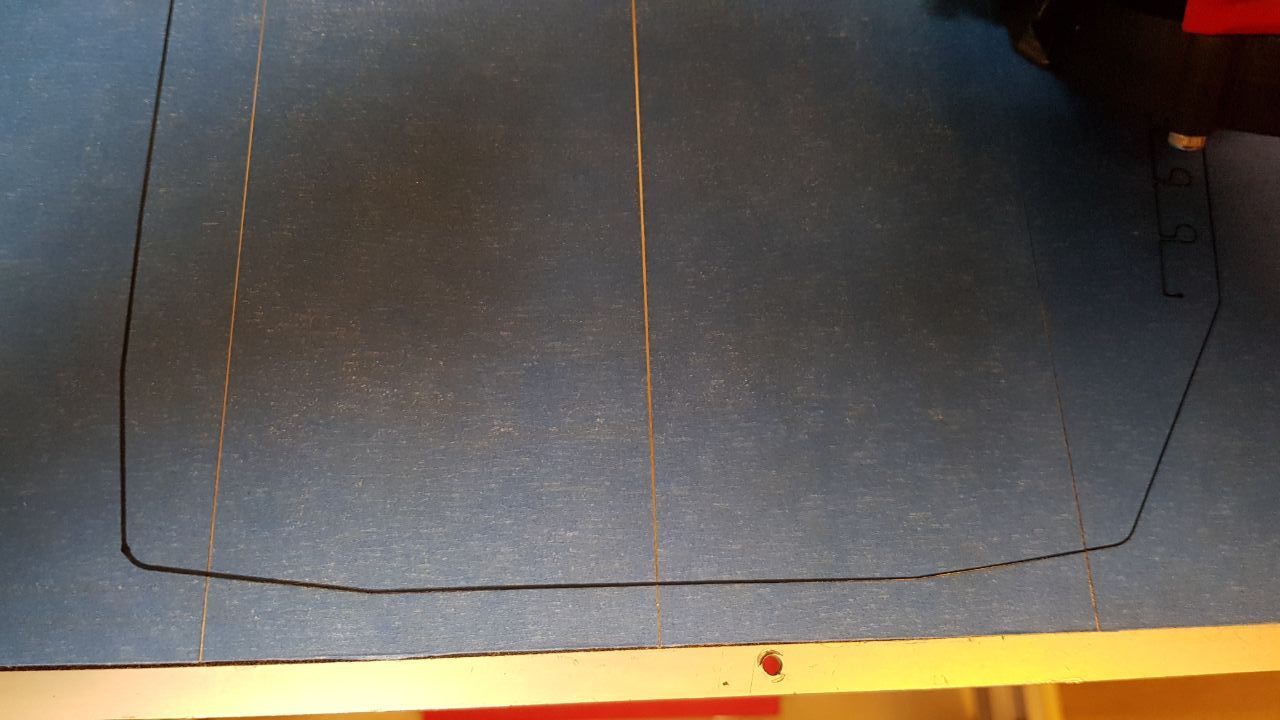
If I check the level map, the board is aware about that the left side is a bit higher than the right (slightly, but there is a difference). It doesn´t matter the amount of points that I use, and if I repeat G29, the results are consistent:
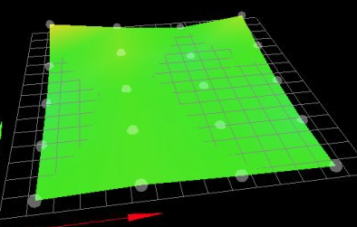
Note: First point left (same as Z Home) is 0.003, second row highest point is 0.025I've two Z motors (left and right) and this is the config and Z config that I'm using: https://github.com/aimartin/duet3DConfig/tree/master/Hypercube
Board: Duet 2 WiFi (2WiFi)
Firmware: RepRapFirmware for Duet 2 WiFi/Ethernet 3.01-RC10 (2020-04-25b3)
Duet WiFi Server Version: 1.23In my Gcode I've a G29 S1, and I always manually execute G32 and G29 before each print....
Am I doing something wrong?
Thanks
-
If you’re sure you’re probing the area printed, It’s possible the mesh resolution is not small enough to pickup some of the finer details of your bed. Recommend changing the M558 parameters to be S20. This will do a 400 point mesh and will be the finest mesh detail possible, then running the same test print. If you are still seeing first layer inconsistencies, then you will need to look elsewhere.
-
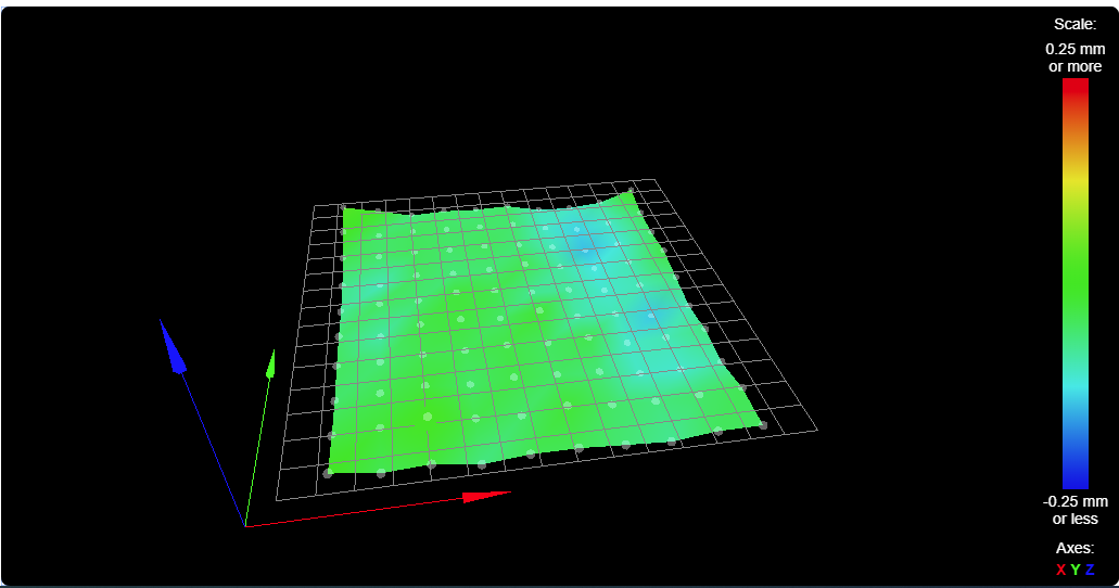
I've tried with a 10x10 mesh, and yes, I'm probing the correct zone... and the results are the same, filament is less squashed in the right side of the bed

Regards
-
I'd ask you link your bed.g file, your start code you may have in your slicer, and to check if there are any override.g file that may be affecting the use of the mesh.
-
@okercho said in Mesh bed Levelling with BLTouch. Am I doing something wrong?:
https://github.com/aimartin/duet3DConfig/tree/master/Hypercube
It makes it a lot easier to troubleshoot if you post all the file contents directly into your post using the code blocks.
bed.g
;G28 X ; home X
;G28 Y ; home Y
G28 Z ; home Z
G1 X5
G30 P0 X25 Y165 Z-99999 ; probe near a leadscrew, half way along Y axis
G30 P1 X290 Y160 Z-99999 S2 ; probe near a leadscrew and calibrate 2 motors
G28 Z ; home Z
;G29 ; Mesh Bed Levelling
; Configuration file for Duet WiFi ; executed by the firmware on start-up ; General preferences G90 ; send absolute coordinates... M83 ; ...but relative extruder moves M550 P"Hypercube" ; set printer name G21 ; Work in Millimetres M669 K1 ; select CoreXY mode M555 P2 ; set compatibility with Marlin ; Network M552 S1 ; enable network M586 P0 S1 ; enable HTTP M586 P1 S1 ; disable FTP M586 P2 S0 ; disable Telnet ; Drives M569 P0 S1 ; physical drive 0 goes forwards (X) M569 P1 S1 ; physical drive 1 goes forwards (Y) M569 P3 S0 ; physical drive 3 goes forwards (Extruder) M569 P2 S1 ; physical drive 2 goes forwards (Z Right) M569 P4 S0 ; physical drive 4 goes forwards (Z Left) M584 X0 Y1 Z4:2 E3 ; set drive mapping ZLeft:4 ZRight:2 M671 X-50:335 Y165:160 M350 X256 Y256 I0 ; configure microstepping without interpolation for X and Y M350 Z256 I0 ; configure microstepping without interpolation for Z M350 E16 I1 ; configure microstepping with interpolation for Extruder M92 X1280.00 Y1280.00 Z6400.00 E144.83 ; set steps per mm M566 X900.00 Y900.00 Z12.00 E120.00 ; set maximum instantaneous speed changes (mm/min) M203 X6000.00 Y6000.00 Z200.00 E2500.00 ; set maximum speeds (mm/min) M201 X700.00 Y700.00 Z50.00 E250.00 ; set accelerations (mm/s^2) M906 X1400 Y1400 Z1000 E1300 I30 ; set motor currents (mA) and motor idle factor in per cent M84 S30 ; Set idle timeout ; Axis Limits M208 X0 Y-5 Z0 S1 ; set axis minima M208 X275 Y300 Z260 S0 ; set axis maxima ; Endstops M574 X1 S3 ; set endstops controlled by motor stall detection M574 Y1 S3 ; set endstops controlled by motor stall detection ; Z-Probe M307 H3 A-1 C-1 D-1 ; DISABLE HEATER 3 for BLTouch M98 P/macros/Z_Config ; Execute macro for Z config ; Heaters M140 H0 M308 S0 P"bed_temp" Y"thermistor" T100000 B4138 R4700 ; set thermistor + ADC parameters for Bed M950 H0 C"bedheat" T0 ; create heater for Bed M307 H0 A194.6 C473.2 D1.4 S1.00 V24.2 B0 ; heating parameters for Bed M143 H0 S80 ; set Temperature Limit for Bed to 80 M308 S1 P"e0_temp" Y"thermistor" T100000 B4750 C7.060000e-8 R4700 ; set thermistor + ADC parameters for heater 1 M950 H1 C"e0_heat" T1 ; create heater for Extruder 1 M307 H1 A593.1 C230.0 D4.6 S1.00 V24.0 B0 ; heating parameters for Extruder 1 M143 H1 S245 ; set temperature limit for Extruder to 245C ; Fans M950 F0 C"fan0" ; create Fan0 (Layer Fan) M106 P0 S0 I0 F500 H-1 ; set fan 0 value, PWM signal inversion and frequency. Thermostatic control is turned off M950 F1 C"fan1" ; create Fan1 (E3D Fan) M106 P1 S1 I0 F500 H1 T45 ; set fan 1 value, PWM signal inversion and frequency. Thermostatic control is turned on ; Tools M563 P0 D0 H1 F0 ; define tool 0 G10 P0 X0 Y0 Z0 ; set tool 0 axis offsets G10 P0 R0 S0 ; set initial tool 0 active and standby temperatures to 0C ; Custom settings are not defined; homeall.g ; called to home all axes ; M400 ; make sure everything has stopped before we make changes M915 X Y S2 R0 F0 ; set X and Y to sensitivity 2, do nothing when stall, unfiltered M574 X1 Y1 S3 ; set endstops to use motor stall G91 ; use relative positioning ;G1 Z10 F1200 ; lift Z G1 S1 X-325 Y-325 F3600 ; move right/back 325mm, stopping at the endstop G1 X5 Y5 ; move away from home ; X or Y is homed at this point, now home the other axis G1 S1 X-325 F3600 ; move towards axis minimum G1 S1 Y-325 F3600 ; move towards axis minimum G1 X5 Y5 ; move away from home ;G1 Z-10 F1200 ; lower Z M400 ; make sure everything has stopped before we reset the motor currents G90 ; back to absolute positioning M574 X1 Y1 S1 ; define active low microswitches G92 Z0; homex.g ; called to home the X axis ; M400 ; make sure everything has stopped before we make changes M915 X S2 R0 F0 ; set X and Y to sensitivity 12, do nothing when stall, unfiltered M574 X1 S4 ; set endstops to use motor stall G91 ; use relative positioning ;G1 Z10 F1200 ; lift Z G1 H1 X-325 F3600 ; move right/back 325mm, stopping at the endstop G1 X5 ; move away from home M400 ; make sure everything has stopped before we reset the motor currents G90 ; back to absolute positioning; homey.g ; called to home the Y axis ; M400 ; make sure everything has stopped before we make changes M915 Y S4 R0 F0 ; set X and Y to sensitivity 2, do nothing when stall, unfiltered M574 Y1 S4 ; set endstops to use motor stall G91 ; use relative positioning ;G1 Z10 F1200 ; lift Z G1 H1 Y-325 F3600 ; move right/back 325mm, stopping at the endstop G1 Y5 ; move away from home M400 ; make sure everything has stopped before we reset the motor currents G90 ; back to absolute positioning; homez.g ; called to home the Z axis ; ; generated by RepRapFirmware Configuration Tool v2.1.3 on Tue Dec 03 2019 18:48:42 GMT+0100 (hora estándar de Europa central) ;*** Configure Z Probe -------------------------------------------------- THIS OVERRIDES THE CONFIGURATION OF CONFIG.G! M98 P/macros/Z_Config ;*** Home Z Axis -------------------------------------------------------- M98 P/macros/Home_Zhomez G1 X0 Y5 F5000 ; Move X and Y to the Z Homing Point G30 ; Single Z Probe G1 Z10 ; Raise Z to 5 mmconfig z M561 ; Delete actual mesh ; Numero + Alto = Mas pegado a la base ; Numero + Bajo = Mas despegado de la base ; PINDA ; ;M558 P5 C"^zprobe.in" F150 R0 T6000 H3 A5 S0.007 ; Tipo 5, Speed 150mm/m, Recovery 1, Altura 3, Velocidad Travel 3000mm/min, Max 3 Retries ;M557 X25:290 Y10:300 P3 ; PINDA ;G31 X25 Y0 Z1.600 ;PINDA Prusa - 1.551 - 0.15 ; IRDA ; ;M558 P1 C"^zprobe.in" F70 R0 T6000 H4 A5 S0.007 ; Sensor IR ;M557 X25:290 Y10:300 P7 ; IR ;G31 X25 Y0 P500 Z2.476 ; BLTOUCH ; M558 P9 C"^zprobe.in" H3.2 F50 T8000 A10 R0.75 S0.005 ; B1 M950 S0 C"exp.heater3" M557 X25:290 Y5:295 P4:5 G31 X25 Y0 P25 Z3.875 ; Z3.720 (Buildtak) | Z3.880 (AzulMin) -
Looking at how your gcode is linked together I think the issue is that in bed.g you have g28 Z, which calls homez, which calls 2 other macros, which is different than the behaviour of homeall. Also, homeall doesn't appear to home the Z axis at all.
You need to go through your order of operations and follow along with what's being executed.
I also see that you have some of your endstop configuration etc in your homing files. This is fine, but you need to be careful that when you change something it's not going to be overwritten later on by a different file.
to track this down I would suggest executing all of your macros line by line manually in the order that you would normally. And if you notice you're sending the same gcode again later with different values you might find that you're changing something you shouldn't be.
-
Hi,
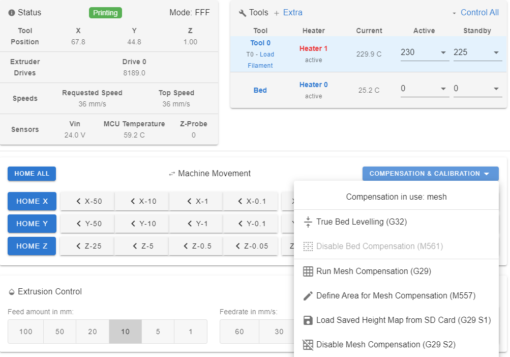
Thanks, I'll try to make it more simple so I can debug it, although checking the compensation and calibration in the GUI, it seems that mesh is being used (I'm executing G29 S1 in my gcode):
Regarding the homeAll, I'm not using it... Im doing the homing "manually" (First homing X, then Y, and then Z, one by one), after that, I do the G32 and G29, and then if everything was successful, I launch the print... I got used to do it in that way when I was using a non-very-reliable probe some time ago...
Regards
-
What do you have in your slicer start gcode?
-
Seems to be the exact same problem I have. My IR Probe scans the bed, reports properly, but when printing, it ignores it.
-
@okercho
What happens if you add to the start fo bed.g ?M290 R0 S0 ; clear baby stepping M561 ; clear any bed transform -
Same problem for me with bltouch.
I follow the post -
Hi all,
At least I'm not the only one so... we're all doing something weird

This is my start code, is based on the Prusa one (I'm using PrusaSlicer)
G90 ; use absolute coordinates M83 ; extruder relative mode ;G32 ; Bed Level {if first_layer_bed_temperature[0] > 0} M140 S[first_layer_bed_temperature] ; set bed temp M190 S[first_layer_bed_temperature] ; wait for bed temp {endif} G29 S1; mesh bed leveling M104 S[first_layer_temperature] ; set extruder temp M109 S[first_layer_temperature] ; wait for extruder temp G1 X40 Y100 F5000 G1 Y0 Z0.6 F3000.0 ; go outside print area G92 E0.0 G1 Z0.2 X30.0 E9.0 F1000.0 ; intro line G1 X100.0 E12.5 F1000.0 ; intro line G92 E0.0 M221 S{if layer_height<0.075}100{else}95{endif}Regards
-
@OwenD said in Mesh bed Levelling with BLTouch. Am I doing something wrong?:
M290 R0 S0 ; clear baby stepping
M561 ; clear any bed transform
I've changed my bed.g for this and report back, although as I'm using G32 right after starting the printer, I don't think this will apply
M290 R0 S0 ; clear baby stepping
M561 ; clear any bed transform

;G28 X ; home X
;G28 Y ; home Y
G28 Z ; home Z
G1 X5
G30 P0 X25 Y165 Z-99999 ; probe near a leadscrew, half way along Y axis
G30 P1 X290 Y160 Z-99999 S2 ; probe near a leadscrew and calibrate 2 motors
G28 Z ; home Z
G29 ; Mesh Bed Levelling
Regards
-
Is there a reason why your probe points for the lead-screws do not share the same Y values? One is 165 the other 160.
Also looking at the two meshes that you provided there is something odd going off. The first (lower resolution) mesh shows part of the bed to be "above zero" with the rest below, the second (higher resolution) mesh shows pretty much all of the mesh "below zero". That does not seem correct to me.
-
One possible issue is that you are doing g32 and g29 before the printer is up to temp. Recommend moving the g32 after the nozzle and bed heating commands.
Most likely your printer and bed dimensions are slightly changing due to probing before everything up to temp. Try to probe as close as possible to printing so things don’t change from where the printer thinks thing are to where they actually are now.
-
@gloomyandy said in Mesh bed Levelling with BLTouch. Am I doing something wrong?:
Is there a reason why your probe points for the lead-screws do not share the same Y values? One is 165 the other 160.
Also looking at the two meshes that you provided there is something odd going off. The first (lower resolution) mesh shows part of the bed to be "above zero" with the rest below, the second (higher resolution) mesh shows pretty much all of the mesh "below zero". That does not seem correct to me.
Regarding the different Y, the printer is a CoreXY with 2 lead-screws. When I checked for the Y position for the G32, I discovered that the motors were not perfectly aligned, and that's reflected in the bed file.
About the image, the bed is magnetic, is an aluminum heated bed, with a glass on top that has the magnets on it (Buildtak) and the steel sheet on top. I'm assuming that even though I put the sheet always the same way, the measurements changes. I'm doing always a G32 and a G29 after removing and installing the sheet, and if I repeat the G29 (without removing the sheet), results are consistent.
Regards
-
@mwolter said in Mesh bed Levelling with BLTouch. Am I doing something wrong?:
One possible issue is that you are doing g32 and g29 before the printer is up to temp. Recommend moving the g32 after the nozzle and bed heating commands.
Most likely your printer and bed dimensions are slightly changing due to probing before everything up to temp. Try to probe as close as possible to printing so things don’t change from where the printer thinks thing are to where they actually are now.
I'm not always using the heated bed. When I do, I put the bed on, wait for it, and then home Z and perform the G29, as I´ve noticed, as you said, that bed expands (and as I've several "layers", it needs more time to reach the temp on top).
Regarding the nozzle temp, as I'm using a BLTouch, the nozzle temperature is not "important", I just have it into account for the G31 command.The problem is that, checking the raft, it doesn't seems to be applying the compensation... even though as per the heightmap, the printer is aware of it :S.
Regards
-
An easy way to check if the mesh is applied is to watch the z steppers for the first layer. They should move slightly if mesh compensation is enabled.
-
@mwolter said in Mesh bed Levelling with BLTouch. Am I doing something wrong?:
An easy way to check if the mesh is applied is to watch the z steppers for the first layer. They should move slightly if mesh compensation is enabled.
I did... I can see the left side still more squashed and I cannot see the motor moving (I've put a bit of tape and I´ve been observing it, and I think it didn't move at all...)
-
@okercho When you are printing, if you go to the 'Dashboard' and click the 'Compensation & Calibration' button, what does it say at the top of the dropdown?
If mesh compensation is enabled it should look like this.
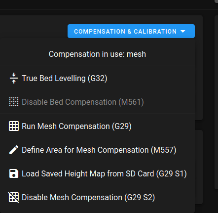
Compensation in use: meshP.