@dc42 pullup resitor between expansion pin 43 and E3_stop, switch between E3_stop and ground? (I already used the nearby 3.3v pin 3)
.
.
.
5min later.
Yes, This works with a 10KΩ ....
Posts made by Yao
-
RE: sensitivety of E2(pin9) and GND(pin2) on expansion as to E1posted in Duet Hardware and wiring
-
RE: sensitivety of E2(pin9) and GND(pin2) on expansion as to E1posted in Duet Hardware and wiring
@dc42 any way to do this without adding parts?
Is there another (set of) free pin(s) I can use with the switch wired as is? (E0 and E1 stop are used, as are all standard endstop pins.)I did switch to the shielded cable to the E3 (pin9/ GND-pin2) but this dd not solve it. another machine layed out like this with much shorter wires does work.
The strange thing is that when I test wire it on E3 (pin9/ GND-pin2) with a10cm wire+NCswitch. I also get inconsistent response. echo states are Always 0 pressed or unpressed. However, when I switch, the board does trigger...
-
RE: sensitivety of E2(pin9) and GND(pin2) on expansion as to E1posted in Duet Hardware and wiring
@T3P3Tony Thanks! That explains it all. i now know how to mitigate this
-
sensitivety of E2(pin9) and GND(pin2) on expansion as to E1posted in Duet Hardware and wiring
Is the EM sensitivety of a simple endstop switch connected to E2 (pin9) and GND(pin2) on the expansion higher compared to the same endstop switch connected to E1_Stop (E1 and GND)?
I am getting unexpeceted results in reading the switch connected to E2. That wire is 60cm longer,,, (260cm compared to 330 cm... that extra 60cm length is unshielded but twisted.Running Duet wifi with 3.4.6
-
RE: Printer name as global variable used with M550posted in Gcode meta commands
@T3P3Tony the echo worked... but in the config.g that M550 was in the wrong location...
I use an external file with all globals, this was loaded after the M550 command,
...I was not paying attention... -
RE: Printer name as global variable used with M550posted in Gcode meta commands
my bad.
line was before global !!!!
-
RE: Printer name as global variable used with M550posted in Gcode meta commands
@T3P3Tony it just returns the name to : My Duet...
I cant even get
M550 P{global.AccName}
to work...
i dont get it. -
DWC system folder paswordposted in Duet Web Control
Re: DWC system folder password?
I still thinkt this would be a welcome adition.
blocking direct access to this folder would protect it from users who do not know what they are doing.
students using a printer running Duet sometimes find themselves in the sys folder clicking something.
Clicking on something in the sys folder opens the file in editable form, some text can accidentally be injected and saved... with all undesired effectsYes, it would not allow for full pretection.
But it would be a small hurdle you can't 'accidentally' cross. -
Printer name as global variable used with M550posted in Gcode meta commands
hi, does anyone know how i can use multiple global variables into one string with the M550 (printername)?
global AccName="Myprinter"
global serial="467"How to combine these two behind the: M550 P.....
Thanks!
-
RE: IR surface mesh issues between firmware 3.2.2 an 3.4.6posted in General Discussion
@Yao I think this was solved by reducing the probing speed to a maximum of F400
-
RE: Z position changes after X or Y home - RRF 3.4.0posted in Tuning and tweaking
@fcwilt Hi Frederick,
When the surface is not flat (1 side is much higher compared to the other ) or even curved, after scanning the surface we can still print over it properly as the nozzle will follow the scanned mesh.Our Z end stop is the same as the IR probe. IRprobe = Z end stop.
-
RE: IR surface mesh issues between firmware 3.2.2 an 3.4.6posted in General Discussion
@droftarts Hi Ian,
thanks! for the response, I used a LUTUM for the above tests. Stationary bed.
duet wifi 2.
max speed change for Z = 50 mm/min
max speed for Z = 1300 mm/min
accelerations for Z = 20 mm/s^2i dont think these are the issue, printing itself is fine with or without using the mesh data.
its just that the mesh data itself does not represent the actual surface.i went over the differences between 3.2 and the following firmwares.
"Use the new M558 facility to do fast-then-slow probing instead" unfortunately this is a much slower process.i also found this:
"The object model for the height map (move.compensation.probeGrid) has changed"
"The height map file format has been extended. Height maps generated by earlier versions of RRF can still be loaded by this version, but height maps generated by this version of RRF cannot be loaded by earlier versions."anyways, I ran a super slow probe sequence with 3.4.6
M574 Z1 S2
M558 P1 C"zprobe.in+zprobe.mod"h5 F50 T6000
G31 P515
M557 X5:170 Y5:210 S40
M376 H20
and now its somewhat ok.
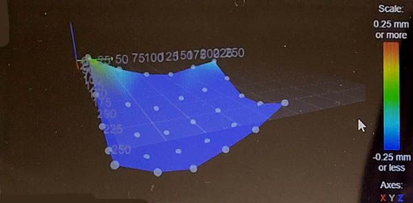
its unfortunate it needs to run this slow to work properly
ill try and find the upper speed limit. -
IR surface mesh issues between firmware 3.2.2 an 3.4.6posted in General Discussion
Our printer is running perfect with 3.2.2 but i maybe an update (its 2024 now) would be good.
After upgrading to 3.4.6 all works fine except the bed adhesion of the first layer.
The further away from XY 0,0 i print the worse the surface adhesion isI am using a IR surface scan prior to every print as we swap the printsurface between prints.
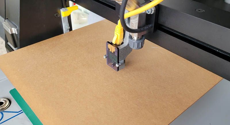
These printsurfaces are never regular (plaster) and need to be scanned for good first layer adhesion.For testing the observed issue i just used a piece of PMMA covered with paper. It is not flat, corners are curved up little: ( the plaster the PMMA is resting on is a bit wet and the paper cover on that side absorbed the water expanding that side of the PMMA) bat that should not matter for the scan.
I just apgraded a printer to 3.4.6 firmware and noticed a diviation in the YZ direction while printing
after trying a lot of calibration i started measuring the actual values from the mesh and they are off.When changing the firmware back to 3.2.2 this is the mesh result is what is should be
I did not alter anything else, only the firmware. The printer behaves as it should.scan in 3.2.2:
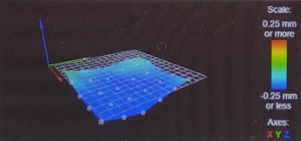
3min later exact same scan in 3.4.6:
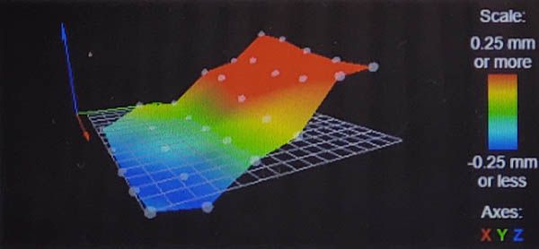
deviation is only in the Y direction. The relative point differences along X are somewhat similar between firmwares.
I have been trying to figure out what to do to compensate this mesh results but sofar i can't seem to find a logical reason. Do I need to change any values in any config files for the 3.4.6 firmware to work as the 3.2.2 in relation to Bed mesh or IR config?
in config.g:
M574 Z1 S2
M558 P1 C"zprobe.in+zprobe.mod"h5 F1000 T6000
G31 P515
M557 X5:170 Y5:210 S40
M376 H20
I also notice that dive speeds andgeneral sensing behaviour are different between firmware.
Homing Z with 3.4.6 is also faster, it just keeps going full speed down and abrubtly stops at about 5mm above the surface.
In 3.2.2 the homing is fast untill the IR senses the surface about 15mm above it, then it slows down untill it hits the P515 value at about 5mm above the surface.Is this a setting I now need to adjust somewhere?
1 hour later: tried 3.4.5 but that one is even worse:
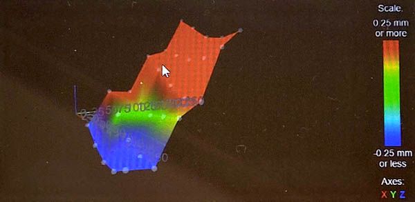
3.3 is different again:
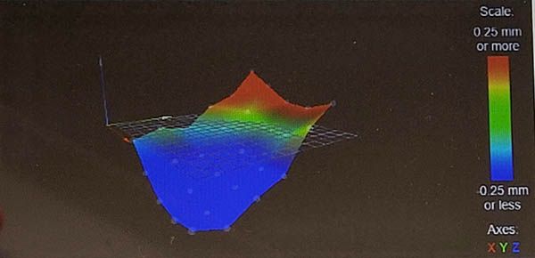
-
RE: Z position changes after X or Y home - RRF 3.4.0posted in Tuning and tweaking
@fcwilt we sometimes print on a sloped surface. if the position away from 0 is lower and homing is not compensated the head would crash into the printsurface.
we always lift the head about 10 mm before homing so never had an issue. But it could give an issue if the slope is over 10mm. -
RE: Z position changes after X or Y home - RRF 3.4.0posted in Tuning and tweaking
@Nicolas-BOYARD yes same here, running 3.4.6
I just tested your issue, i can confirm after every home X or Y it adds an ofset to Z.
Then moving Z to 0 leaves a visible gap and a Z offset in the coordinate.
In guess homing with G1 and H variable does not use the mesh data.I was searching for an unexpected Y offset after a mesh bed session. After probing, the further away i get from 0 in the Y direction the higher Y offsets. X is not affected.
Cant find the issue here in the forumUsing an IR probe to run the mesh.
Same probe is used for Z0 height. -
Adjusting extruder rotation speed.posted in General Discussion
Adjusting extruder rotation speed.
The extruder setup I have uses 4 motors combined into 1 tool:
M563 P0 D0:1:2:3
This works, all motors turn at the same speeds at any given time extrusion is needed.The problem starts when I want to maually adjust the extrusion speed by increasing or decreasing the speeds the motors rotate at.
If I use the paneldue interface and change the percentage of extruder 1, only motor 0 changes in speed. All others are unaffected.
The current solution is to manually adjust all extruder motors in DWC to the same value.
Is there a setting I am missing or some config adjustment I can make so the motors all respond to the single percentage adjustment?
further on this, lets say I have adjusted the motors to some manual mix rate but want to adjust the combined flow up or down, how do I set all motors to adjust at the same time without me having to calculate the new combined adjusted percentages...?
I bet there is an easy solution I overlooked....
-
RE: software CAN check & CAN connection reset if needed?posted in Gcode meta commands
@dc42 swapped for 4 of these https://www.damencnc.com/userdata/file/5205-1_EM882S_User_Manual_V1.pdf
Very smooth and fast movement but haven't seen if there is feedback. This system does not allow the drivers powered without the board also powered first. -
RE: software CAN check & CAN connection reset if needed?posted in Gcode meta commands
@dc42
I have been running this for a long time, once its up and running it seems to work fine.
Can it damage any components?
I am very happy with the leadshine performance...
What if I power the 1XD's direct from the leadshine?Otherwise what driver would you recommend for the 1XD, Needs to be capable of DC-70v
-
RE: software CAN check & CAN connection reset if needed?posted in Gcode meta commands
@dc42 ok, this is the setup. Proto picture with the leadshine powerd and the duet unpowered left. In the final setup this is no longer possible as the DUET always powers up about 12 sec before the leadshine receives its power.
http://leadshineusa.com/UploadFile/Down/MX4660d_V1.1.pdf
Page 9, par.8.2:
on 1XD the Step+ is linked to leadshine pin 2 (X axis step)
on 1XD the Dir+ is linked to leadshine pin 3 (x axis dir)This follows trough for YZU axis
Then on the 4th (last in line) 1XD I had to connect a ground wire from leadshine (pin 21) to D0_step(-) for this system to work.
if I connected any other 1XD to a ground wire the rest after it would not work.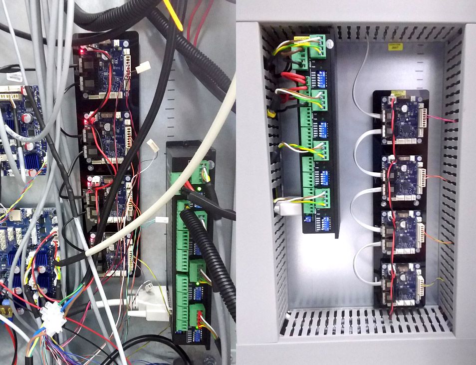
As you can see in the left picture, after powering up leadshine, all 4 1XD board light up slightly.
They do not receive power from their own 24v source.
A bit unconvential maybe, but the source power for the 1XD array is OUT1 from main DUET3, If I find that any 1XD driver lost CAN connection (happens somtimes), I can reset the array with a trigger while leaving DUET and 3HC powered. -
RE: How can I create a toggle macro?posted in Gcode meta commands
@owend @owend Never had such a clear explanation is this!
But, is there a clear 'roadmap' where i can find all these specific DUET adresses, numbers, extensions and designations?
Where can I find the 'object model browser' :
this ?: https://github.com/Duet3D/RepRapFirmware/wiki/Object-Model-Documentation#overview
I can't find the specific addresses you mention in that list.
M409 gives me an empty list of strings...