@dc42 The chamber and the cooling fans are 5 very large blower fans, could the temperature change when opening the door be explained by a lower pressure in the chamber causing the fans to spin faster and creating more interference?
Posts made by verminsup
-
RE: Thermocouple temperature fluctuations and bad soldering (solved)posted in Duet Hardware and wiring
-
RE: Thermocouple temperature fluctuations and bad soldering (solved)posted in Duet Hardware and wiring
@rjenkinsgb
That must be it, the whole wire is rated thermocouple wire until the last 50cm. My boss wired this machine and had no idea this was a thing with thermocouples, thanks for the reply this has finally convinced him to switch over to regular thermistors.
-
RE: Thermocouple temperature fluctuations and bad soldering (solved)posted in Duet Hardware and wiring
@dc42 This uis the only part that is vissible without taking the machine further apart. The wires go through the cooling duct to the printhead (this is the original desing of the stratasys) The red light is from the config because I've turned that one off.

-
RE: Thermocouple temperature fluctuations and bad soldering (solved)posted in Duet Hardware and wiring
@dc42 Just double checked the wiring and all seems to be in order. I truly wish I could convince my boss to just use some glass bead thermisters on the hotends because those would fit just fine.
-
RE: Thermocouple temperature fluctuations and bad soldering (solved)posted in Duet Hardware and wiring
@dc42 Nothing changes when motors are on or off when It does go down it goes down slowly as the chamber heats up. When this happens onlt the heaters for the chamber are on.
-
RE: Thermocouple temperature fluctuations and bad soldering (solved)posted in Duet Hardware and wiring
@verminsup No it is reading in the correct direction. When I increase the nozzle temperature the reading also increases. I just have no way of knowing when it's hot if the temp is correct or even stable
-
Thermocouple temperature fluctuations and bad soldering (solved)posted in Duet Hardware and wiring
I'm using three old J type thermocuples in my Stratasys Sst 768 duet conversion using two Thermocouple daughterboards. These are the weird things I've seen:
- When the chamber is heating up the two temperatures on the first board go down to between 1c and -3c.
- When I open the door the temperature rises on the two temps under 0
- Using a seperate temperature sensor the room temp is correct, this thermocouple is on the second stacked board while the extruder thermocouples are on the first
- When I switch boards the temperature fluctuations stay the same and the chamber temp stays the same
- After removing the board I noticed a weird almost wet patch on the board
and one of the components was soldered in a bad way. (pics)


Any way to fix this or is this board just bad?
Config for the extruders (don't mind the weird chamber PID)
M308 S0 P"spi.cs0" Y"thermocouple-max31856" T"J" ; configure sensor 2 as thermocouple via CS pin spi.cs2
M950 H0 C"out1" T2 ; create chamber heater output on out0 and map it to sensor 0
M307 H0 A11 C99000 D2000 B1 ; Pid Tune heater 2
M140 H0 ; map chamber to heater 2
M143 H0 S100 ; set temperature limit for heater 2 to 100C
M570 H0 T15 S20000 ; Heater fault detection heater 2, 20000 seconds and 15c differenceM308 S1 P"spi.cs2" Y"thermocouple-max31856" T"J" A"Support" ; configure sensor 0 as thermocouple via CS pin spi.cs0
M950 H1 C"out2" T0 ; create nozzle heater output on out2 and map it to sensor 0
M307 H1 B0 R5.606 C78.0:75.6 D4.59 S1.00 V24.1 ; Pid tune heater 0
M143 H1 S350 ; set temperature limit for heater 1 to 350C
M570 H1 S10 T20 ; Heater fault detection heater 0, 10 seconds and 20c differenceM308 S2 P"spi.cs1" Y"thermocouple-max31856" T"J" A"Material" ; configure sensor 1 as thermocouple via CS pin spi.cs1
M950 H2 C"out3" T1 ; create nozzle heater output on out3 and map it to sensor 1
M307 H2 B0 R5.483 C90.7:90.7 D4.79 S1.00 V24.1 ; Pid Tune heater 1
M143 H2 S350 ; set temperature limit for heater 2 to 350C
M570 H2 S10 T20 ; Heater fault detection heater 0, 10 seconds and 20c difference -
RE: H-bridge dc motor on 1XDposted in Duet Hardware and wiring
Also I got it working just fine but now all of a sudden both drives have stopped working.
Got some very nice prints out of it
-
RE: H-bridge dc motor on 1XDposted in Duet Hardware and wiring
@alankilian
I'm not sure how I can give a specific extrusion amount
By having someone stubborn above me -
RE: H-bridge dc motor on 1XDposted in Duet Hardware and wiring
@o_lampe
I have found this driver.
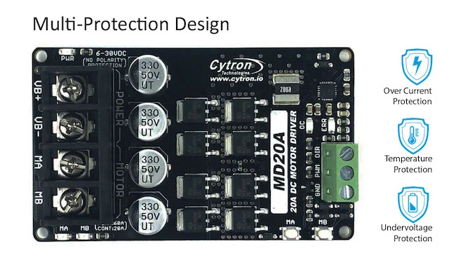
But I'm still not sure how I'm going to let the duet extrude a specific amount.I'll check that driver
-
H-bridge dc motor on 1XDposted in Duet Hardware and wiring
I have been working on a Stratasys conversion for work. They want to use all the original hardware, this includes the Dc servo motors for the extruder. I have been using servo drives together with 1XD boards but now one of the drives is broken and they want me to use a H-bridge for the extruder. I know this isn't a good idea but it's not up to me.
I'm using the L298N
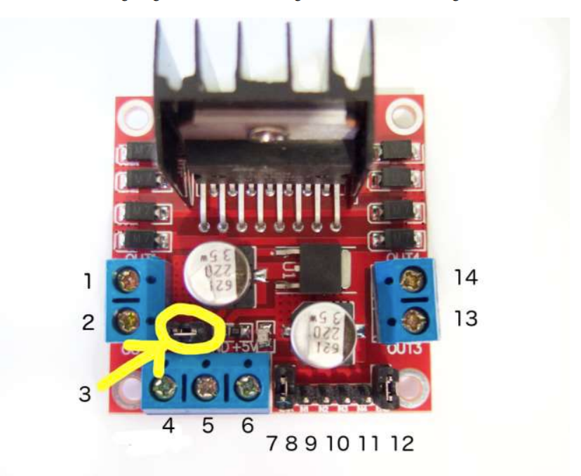
The pins for the stepper driver and how I have them configured right now on the L298N
D0_STEP(-)
D0_STEP(+)
D0_DIR(-) pin 8
D0_DIR(+) pin 9
D0_EN(-) EN-
D0_EN(+)On the L298N I can supply a Pwm signal for speed control on pin 7 and then set the direction with the standard dir pins. I was wondering if the other pins from the 1XD drive give out a pwm signal (and be used for an extruder)? Or is there another way of configuring this like using the fan pwm signal. I was told that the step pins have a pwm signal but I can't set the speed with those.
This is the part of the config that matters for the drive
M569 P0 S1 R0 T4000; -
RE: Servo motor minimum step pulseposted in Tuning and tweaking
@joergs5 Sorry I meant m569. I think I've already tried separate lines but I'll give it another shot
-
Servo motor minimum step pulseposted in Tuning and tweaking
I'm currently running two 1XD boards with two servo drives for two Stratasys servo extruders. I can get both to run perfectly separately but not one after the other because of the minimum step pulse.
In the documentation there is a M589 with a T for minimum step pulse which can be either Taa or Taa:bb:cc:dd while the second parameter after the : usually means that it's for the next drive. When I just mention the one drive that one runs well and when I mention the other that one runs well as well.
How do I mention the second minimum step pulse for the other motor?
-
RE: Brushless Servo using 1XDposted in Duet Hardware and wiring
@dc42 but hom am I supposed to set speed an direction? That might already be enough
-
Brushless Servo using 1XDposted in Duet Hardware and wiring
I'm converting a Stratasys printer for work and my boss want to use the original motors.
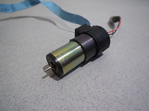
For this I got handed these drives and duet 1XD boards
https://www.faulhaber.com/nl/producten/serie/sc-1801-s/
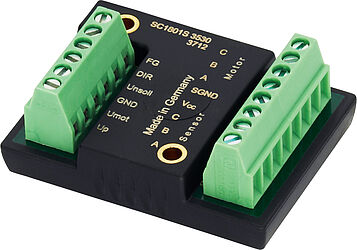
My question is how to correctly wire it, when I know how to wire it I should be able to figure out how to do the config.
Right now my boss has wired it like this:
5v - up
V+ - Umot
Gnd - V-
Unsoll - D0_step(+)
Dir - D0_steo (+) -
RE: JavaScript error when connecting to web controlposted in Duet Web Control
@jay_s_uk
Oh wow that worked, I can't thank you enough.
I was on a tight deadline for getting this to work. -
RE: JavaScript error when connecting to web controlposted in Duet Web Control
@jay_s_uk
Are there any guides for this? All the guides I can find still use the .bin file or want me to upload it through the DWC -
RE: JavaScript error when connecting to web controlposted in Duet Web Control
@jay_s_uk
Duet Wifi
Version 3.1.1 and Version 3.1beta1I have tried both
-
JavaScript error when connecting to web controlposted in Duet Web Control
For some reason after one changed in the config it started saying this.
JavaScript Error
A JavaScript error has occurred so the web interface has closed the connection to your board. It is recommended to reload the web interface now. If this happens again, please contact the author and share this error message:
Version: 1.22.6
Message: Uncaught TypeError: Cannot read property 'toFixed' of undefined
URL: http://---.---.---.--/js/dwc.js (this says the IP adders)
Line: 4468:75
Error object: {}I can still home if I click really fast before getting this message. I have tried a couple of things but nothing seems to help.
- Updated to the latest firmware
- Updated to the beta
- Connected to two different wifi connections
- Used a new sd-card
- Changed with he SD card back what i changed, I removed a heater because I'm using a syringe
The one thing I can think of is updating the DWC but every guide I can find says either to use the web control or is outdated and still usus the Duetwebcontrol.bin file.
I'm at an absolute loss
-
Connecting a Stepper Driver Expansion to a duet 2 wifiposted in Duet Hardware and wiring
I have some spare/extra parts from a different project and I was wondering if there is any way to connect these parts together for more stepper motors
I have:
-Duet 2 wifi
-Maestro Dual Stepper Driver Expansion Module
-Expansion header breakout boardI have looked through the diagrams but I can't figure it out completely with one i could connect tot the Expansion module because some seem to be either missing
Breakout board / Stepper Driver Expansion Module
E2_STEP / E2_STEP
E2_EN / E2_EN
E2_STOP / ?
E2_DIR / E2_DIR
+3.3V / +3.3V
GND / GND
? / VIN
? / E2_UART