Why not use a large value resistor, say 1M, between V- and mains ground?
That will still bleed off a static charge but not, hopefully, impact ground loops as much.
Why not use a large value resistor, say 1M, between V- and mains ground?
That will still bleed off a static charge but not, hopefully, impact ground loops as much.
@dc42 I understand that. The macro early in this thread that takes 10 measurements at the point X151 Y161 works fine in the /sys folder. However, if it is edited to remove the X and Y co-ordinates like:
M291 P"Probe will be tested 10 times and return mean and standard deviation. Ok or Cancel?" R"WARNING" S3 ; User must click OK or cancel.
G28
G30 P0 Z-9999
G30 P1 Z-9999
G30 P2 Z-9999
G30 P3 Z-9999
G30 P4 Z-9999
G30 P5 Z-9999
G30 P6 Z-9999
G30 P7 Z-9999
G30 P8 Z-9999
G30 P9 Z-9999 S-1
it does not stay at the current position but moves in X. I believe it should just take 10 points at the current location without moving.
I also have said professional measuring tools and assumed you did also based on some of our earlier conversations but I was describing a test approach that anyone could implement to check squareness.
@poofjunior I've ordered parts to prototype such a board. I don't know yet if it can be built at the same size as the 2209 board more or less as it would be nice if it could dissipate more current.
I'm targeting 48V.
No idea of cost yet.
@poofjunior I've ordered parts to prototype such a board. I don't know yet if it can be built at the same size as the 2209 board more or less as it would be nice if it could dissipate more current.
I'm targeting 48V.
No idea of cost yet.
What frequency will give the loudest tone on a PanelDue 7"? I'm assuming it is a Helmholtz resonator and is best used with a specific frequency.
@dc42 I understand that. The macro early in this thread that takes 10 measurements at the point X151 Y161 works fine in the /sys folder. However, if it is edited to remove the X and Y co-ordinates like:
M291 P"Probe will be tested 10 times and return mean and standard deviation. Ok or Cancel?" R"WARNING" S3 ; User must click OK or cancel.
G28
G30 P0 Z-9999
G30 P1 Z-9999
G30 P2 Z-9999
G30 P3 Z-9999
G30 P4 Z-9999
G30 P5 Z-9999
G30 P6 Z-9999
G30 P7 Z-9999
G30 P8 Z-9999
G30 P9 Z-9999 S-1
it does not stay at the current position but moves in X. I believe it should just take 10 points at the current location without moving.
The M48 without an X and Y location appears to simply move right to the end of travel.
Could it be changed so that without X an Y, it probes at the current location?
The intended use is:
Probe_Corners.g
; Test repeatability at mesh bed compensation locations
G1 X5 Y5
M48
G1 X300 Y5
M48
G1 X300 Y200
M48
G1 X5 Y200
M48
Reading what I think Lulzbot has done, the big TAZ uses steppers with planetary gears at a ratio high enough that the bed doesn't drop.
The mini Taz I believe uses a relay board that either passes drive or shorts across the windings to brake. The relay is controlled by a power fail circuit that is only activated at power loss.
All this should be available at their site in the development area. I browse it with FTP.
In the first height map, all locations are less than 0.0. What setting would move the center up to Z = 0.0?
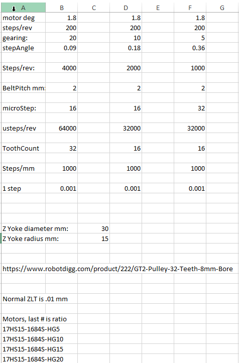
Coincidentally, I just finished yesterday a spread sheet to model a Z belt on a Railcore with the plan of replacing 3 lead screws with 3 motors and belts. The Z yokes are very close to the size of a 16T pulley although it may be possible to offset the pulley as long as the belt that lifts is normal to the yoke. Otherwise, a 32T pulley will work.
I'm specifically looking at OMC Steppers Online and their precision planetary gearboxes seem to only offer 8mm shafts. I've not found a 16T pulley with an 8mm bore.
A 5 to 1 geared motor, 32T pulley and 1/32 microsteps yields 1000 steps/mm. Whether that is realistic in practice remains to be seen.
Note that some of the cheaper motors claim a 5:1 gearing where a careful perusal of the data sheet shows it is actually 5.18:1. That doesn't meet my goal of 1000 steps/mm or any other rational number that I see.
This is not an inexpensive upgrade as the motors are about $42 each.

I also have said professional measuring tools and assumed you did also based on some of our earlier conversations but I was describing a test approach that anyone could implement to check squareness.
@Catalin_RO
You are probably familiar with this trick considering how long you have been working with CNC. Mill or print a maximally sized L square or carpenter's square and then use it to draw a line on a piece of paper with a pencil along the side of L square at a right angle to one edge of the paper. Then flip the square, align it with the same pencil edge and and attempt to draw a line over the previous one. If the are congruent, the CNC or printer is square. If there is a gap at the far end, they the machine is not square. Only an exact 90 degree angle will cause the lines to be the same if the square is flipped. No expensive measuring equipment is required!
So, given a software offset for the individual homing switches, adjust the offset until there is no gap at the far end.