@timschneider In case you are interested, this video offers insight to flow modulated temperature control:
Variable Temperature 3D Printing – The FUTURE of 3D Printing?
@timschneider In case you are interested, this video offers insight to flow modulated temperature control:
Variable Temperature 3D Printing – The FUTURE of 3D Printing?
@bsilver8192 Please look at
https://forum.duet3d.com/topic/36364/feature-adaptive-feedforward-temperature-setpoint/21
You need to loosen heater check even more.
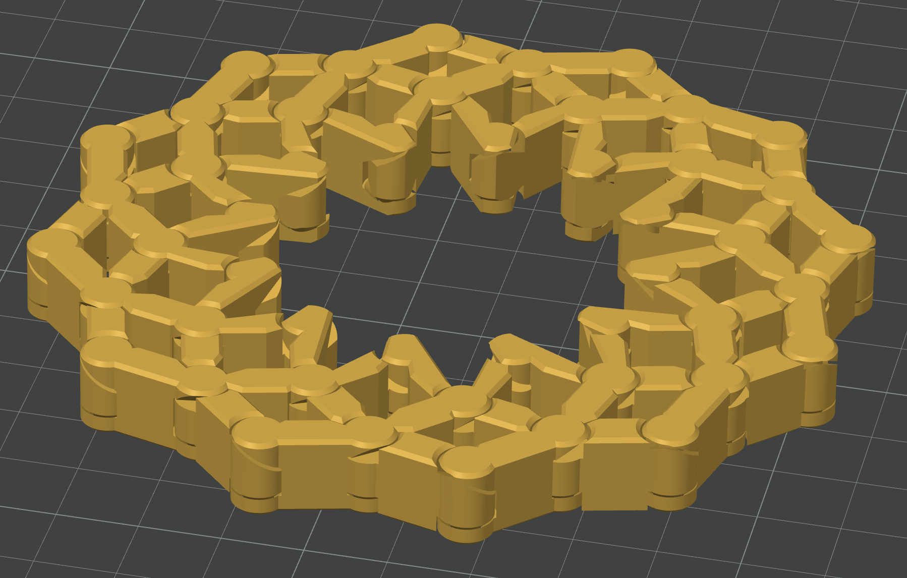
@timschneider That model (I would call it "the "mother of hinges"), went well - all hinges were moving free without play (after forcingly "unfreezing" them the first time). I can infer then than the temperature variation does not pose a danger in maintaining correct dimensions, in this case at least.
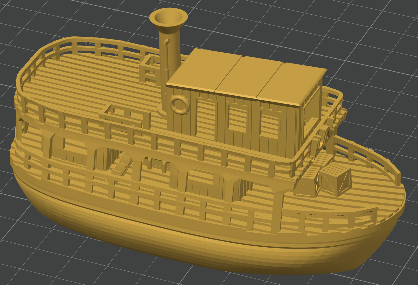
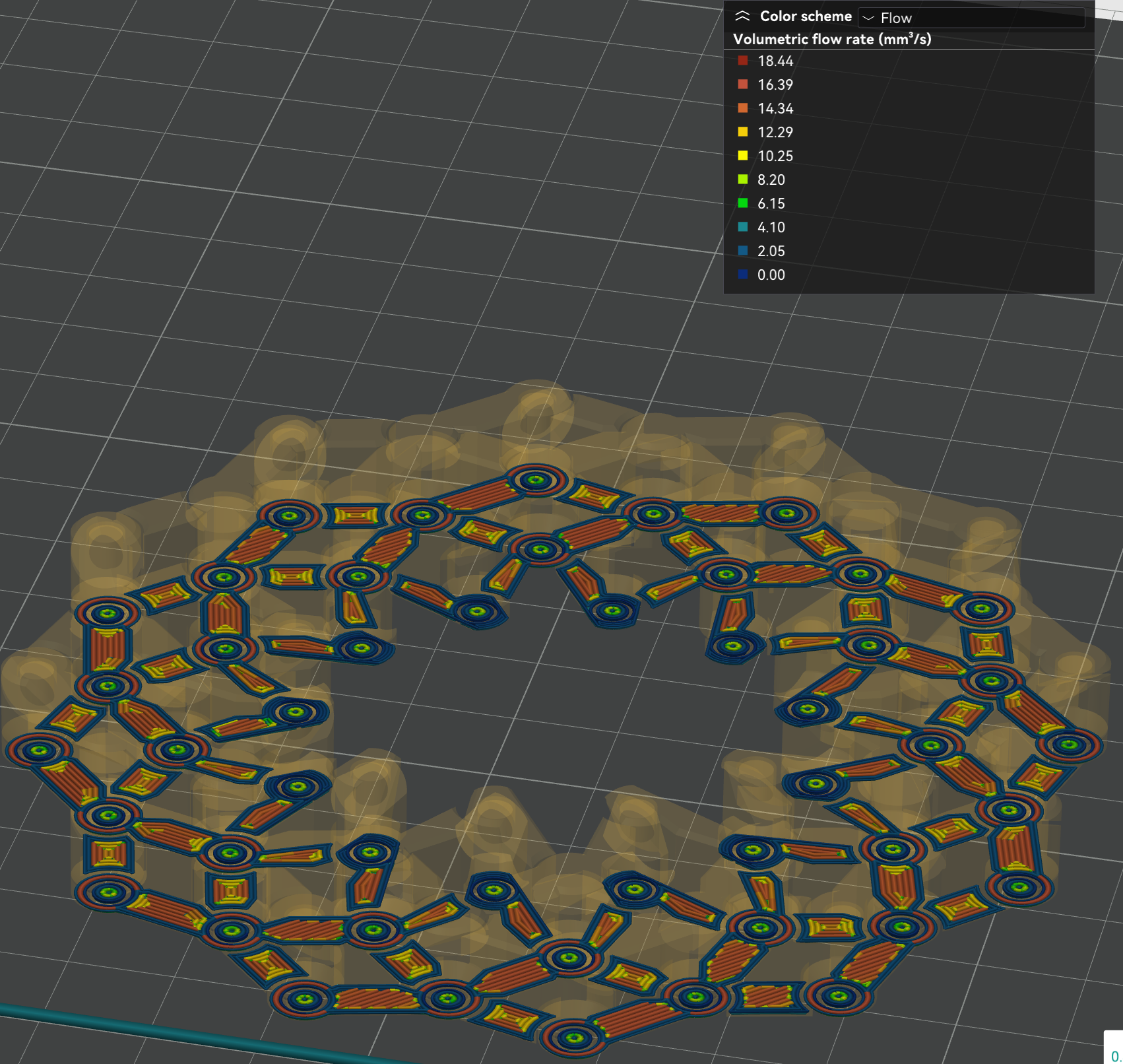
Now I am choosing a more representative test model with an ample variation of flow rate, which at the same time allows us to assess artifacts, without being excessive large or long to print.
This JUN - the Jungle Queen (visual benchy) has a plethora of details and is not too small.
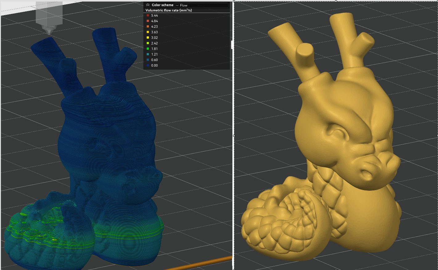
Results:
Printing with at 195 C, 0.2 mm layerheight, (0.4 mm nozzle), solid infill with 0.6 mm layer width, and sparse infill speed set at 300 mm/sec (but not reached) and still using M309 P0 S0.06 T10 A40, Orca Slicer was showing a flow rate up to 29 mm3/s, but that is not true. The real maximum is about 20 mm3/s, enough of a range. Extrusion rate smoothing was set to 90 mm3/s to avoid abrupt transitions.
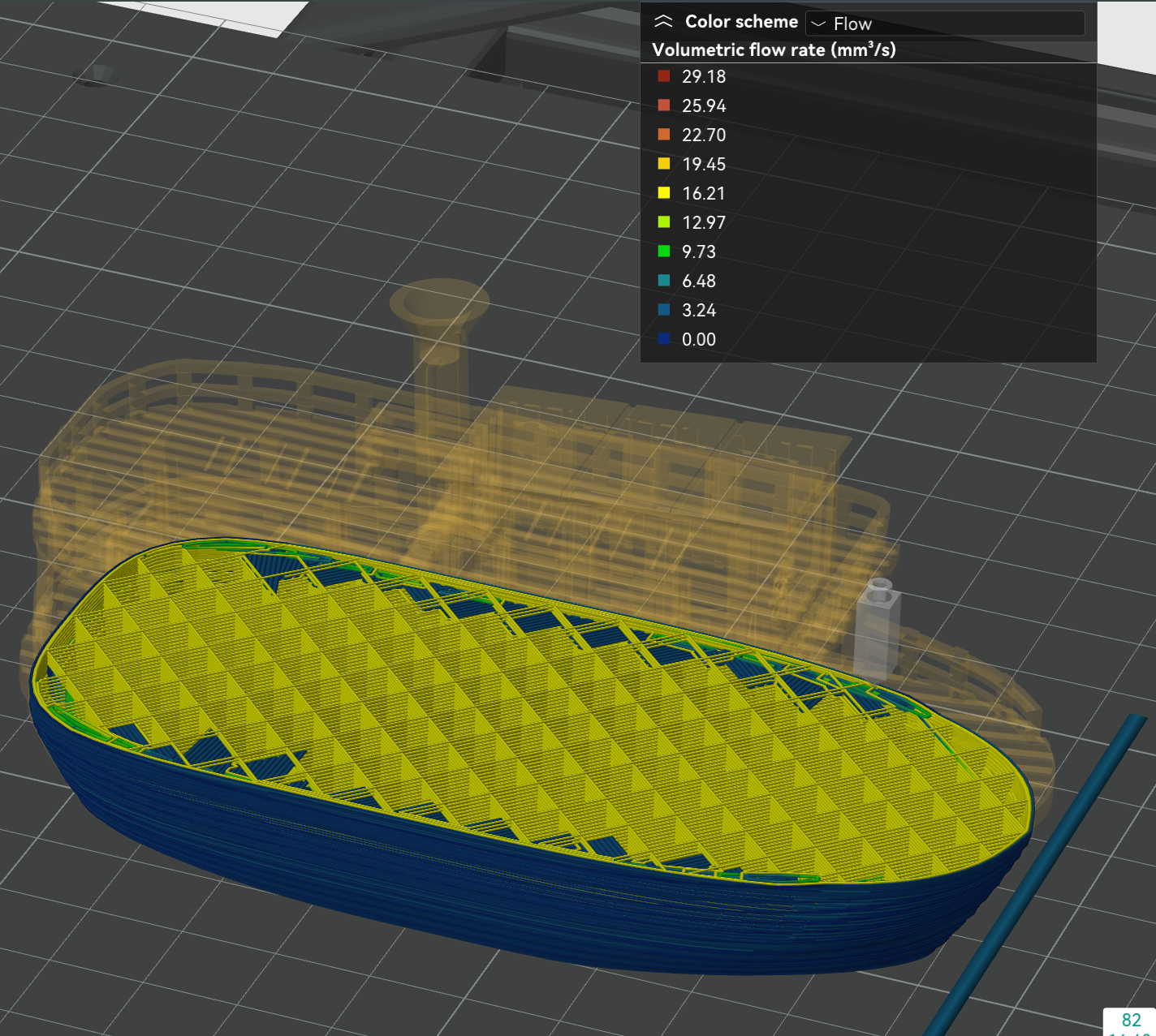
The temperature occassionally reached >240 C in the high flow areas. In very slow areas, it was decreased (!) down to 190 C. Most of the time, is was about 200C.
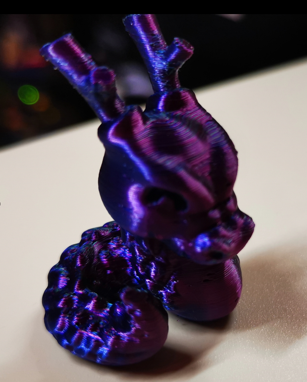
The print shows very crisp details, reminding me of previous cases using the postprocessing script. This is obviously the result of printing the small details with a suiting lower temperature.
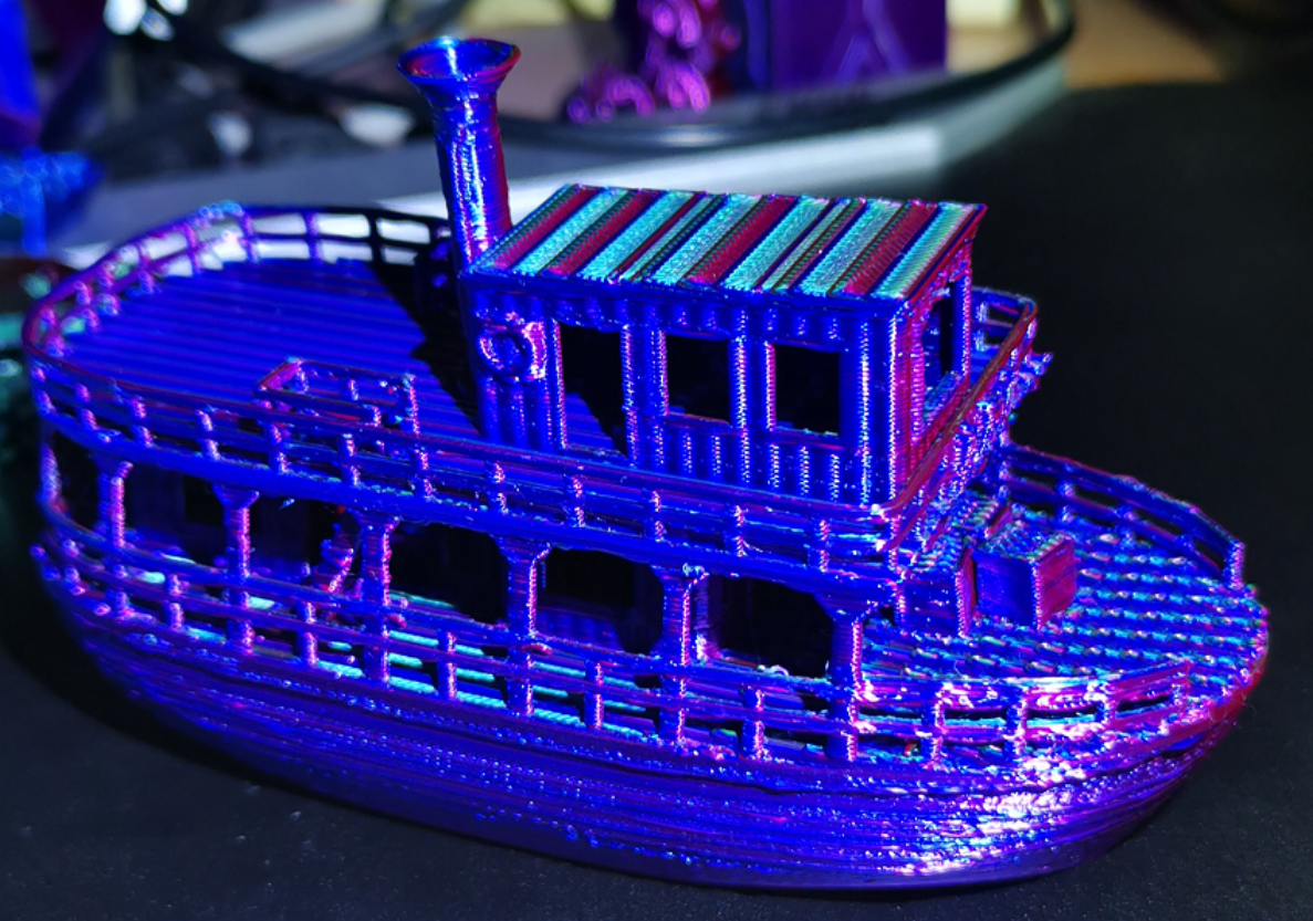
Despite some suboptimal slicer settings (happens when printing in a hurry), the print went well and it looks better than in the picture.
Remarks:
I noticed that right at the begin of the print the temperature is higher than it should be (although I disabled this temperature modulation feature for the first layer), but immediately begins to fall as the print of the 1st layer progresses. My suspicion is that the firmware looks at the flow of the movements in the print queue in advance, but ignoring the command disabling the feature. But the command it is there:
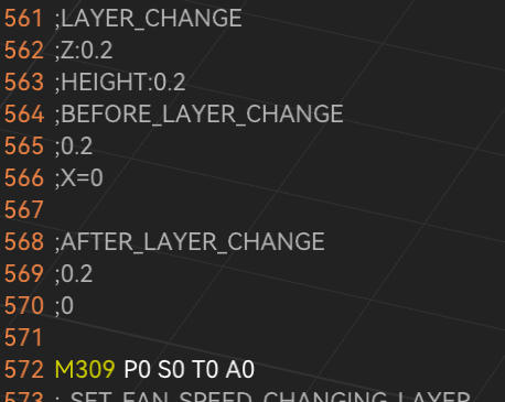
and when it is processed, the temperature fails again to the nominal 195C. It looks like a slip to me.
Furthermore, I still got heater faults (even after releasing the check conditions), but strangely, this happened at a moment where the temperature was quite stable after having significantly changed before. So it looks to me like the firmware notes a temperature deviation, but does not update that deviation timely as the temperature has changed and stabilized. Perhaps that part of the firmware should be revised.
This time, a decrease in temperature compared to the nominally set print temperature (195 C in this case) took place at some point. So I withdraw the objection I made before, although I don't quite understand how this is controlled in detail. I assume that the T parameter defines a slope determined by changes of temperature in relation to changes in flow, but where we are in that characteristic curve, I don't know.
Summarizing, I am very pleased with this enhancement. I still stand on my prediction that this feature will stay extremely underrated. I recommend to try it out.
@timschneider said in [feature] Adaptive / Feedforward Temperature setpoint:
0
This was a test I spontaneously decided to do without planning, but it turned out unsuitable for the purpose of temperature modulation. The maximum flow rate of 5.44 mm3/s (using a 1.75 mm filament) happened very shortly and was not representative at all. I did notice the jump though - causing a heater fault at my first try.
I also use a 60 W heater, in a copper block (E3D style) and an original CHT nozzle. It can achieve a 25C increase faster that one would think, but certainly not fast enough if the model consist of parts with disparate flow rates in succession. And that is exactly the test case I am printing right now:
As you can recognize here:
The temperature is set at 195C but settles at around 199C +/-2C, it can't follow as you say. The range would be much wider if it could. But there are some layers with predominantly high flow, I am waiting to see how the temperature behaves then (I am staring at the display).
Based on my experience using the postprocessing script mentioned above, the maximum temperature lag was about 5C, in most cases only 3C - but that script uses a different method, where the flow rate is adapted (smoothed) to match the predicted temperature, very clever in my opinion. The temperature/flow rate relationship is defined there by entering three points of desired temperature at the given flow rates, quite easy. I could envision that a similar method is implemented in the firmware. But even this T-Parameter is a thing as it is now. I have learned to appreciate the value of temperature control and am quite excited about it.
More tests following.
@dc42
I dared to try 
Using firmware version 3.6.0-beta.4 and with following command in my config.g:
M309 P0 S0.06 T10 A40
I can confirm that temperature modulation based on flow rate works.
I used the small model below as a preliminary experiment, printed at a nominal temperature of 190 deg C. (usually I print this material at 212 deg C).
Remarks:
During the first layer the temperature jumped to over 220 deg C but with the bed at 45 deg C this was unnecessarily high to achieve bed adhesion. To avoid such surprises I managed to disable this feature for the first layer alone using
the macro command
M309 P0 S{(layer_num == 0 ? 0 : 0.06)} T{(layer_num == 0 ? 0 : 10)} A{(layer_num == 0 ? 0 : 40)}
which yields M309 P0 S0 T0 A0 for ths 1st layer only; then the temperature set for the 1st layer in the slicer is used unchanged.
I needed several retries because I was getting a heater fault error right at the 1st layer. The increase was too sudden I guess. Only after I reconfigured the heater fault detection I could continue the print:
M570 H1 P15 T20 ; wait 15 sec, allow 20C deviation
The maximum temperature increase happened at the widest height of the model and was about 5 degrees, but only a short time.
Most of the time the print temperature stayed around 192C, that is, only 2 degrees higher than set. Although the speeds were set up to 300 mm/sec, due to a layer time limitation and weak cooling fan, the print went quite slow with 20-35 mm/sec.
The deviation between target and actual temperatures can't be assessed during the print, because the increase introduced by this feature is done in the firmware - this is as expected, but raises the need of a plug-in in DWC to preview the effect.
Manually overriding the extrusion speed live during the print (or perhaps using M220) did cause a corresponding increase in temperature, as it should be.
It is unclear to me whether extrusion rate increases caused by non-linear extrusion configuration (M592) also cause temperature increases. In theory, his could lead to a vicious circle, because a temperature increase by itself also promotes a higher extrusion.
I learned that this feature works only increasing the temperature, never decreasing it. That means that one is compelled to choose a nominal printing temperature (the one set in the slicer) that should be low enough that no decrease is necessary due to a smallish flow. This could happen to be inconvenient, depending on the average flow and temperature range needed. This method is suitable to adapt temperature in regions with higher flows, overcoming potential bottlenecks.
A better approach would have been (in my opinion) to consider the nominal temperature to correspond to the average flow rate, allowing both increases and decreases. In most cases no special tests or calibrations would be needed with this method; for example, setting 205C for PLA, thus allowing a range of +/- 15C=30C. Flow rate "spikes" would be still accounted for. This way, small details and overhangs would benefit too (a more common concern than printing at very high speeds, if quality is important).
In other words, as it is implemented, you would set for a benchy a nominal temperature corresponding to the chimney top - suboptimal I think.
Print details:
Duet 2 WiFi + 0.4 nozzle, PLA, 0.12 mm layer height, 0.3 mm layer width, one wall only (to challenge the operation!)
And I got this result:
The print was quite good in my opition, and was not worst than a good one done without the feature under same conditions. Still learning.
I have gathered some experience using the post-processing script mentioned above. It is difficult to believe how felicitous that script manages the temperature/flow relationship. That solution works differently though: It controls speeds in such a way that the flow matches the temperature when the temperature can't be changed fast enough; it also smoothes the flow rate - sounds dangerous, but works surprisingly well. Unfortunately, it is only a post-processing script with the respective disadvantages. The author was told that such feature belongs to the firmware realm - here we have it.
I think this feature of the version 3.6.0 will be vastly underestimated. I consider it a big jump, really.
By the way, the description in the documentation of M309 should be corrected. It states:
"This feature is intended for high flow hot ends or pellet extruders. It's not normally needed on regular hot ends with a 0.4mm or similar size nozzle where the temperature drop caused by extrusion is less than 1C."
The feature may be inteded as described, but it is not limited to mere anticipation of temperature fluctuation of the nozzle due to changing flow. In fact, it contributes to a much better control of a key parameter, namely temperature. I myself will be using it quite often, I think.
Hope I helped a bit.
@tas You mean DuetWebControl-SD.zip for sure.
Now that you make me look at the file types, I realize that a bin installs differently than a zip (of course), which is why I didn't see file extraction happening. Thanks.
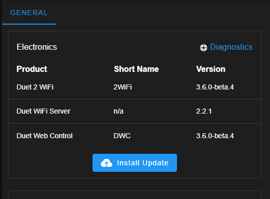
Done:
@T3P3Tony said in [FW 3.5.2] High jerk good for circular path not for corners:
please upgrade all the firmware and software in the system to the same beta version.
Thanks for the remark.
This is what I did: I downloaded Duet2CombinedFirmware.bin from
https://github.com/Duet3D/RepRapFirmware/releases/tag/3.6.0-beta.4
and installed it as usual, but I saw no files being extracted as it usually happens, and the printer was shutoff sooner as usual.
I am using a Duet 2 WiFi board which was at 3.5.4 prior to updating the firmware. After switching the printer on I found:
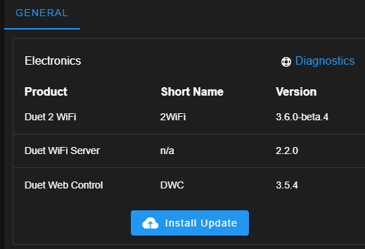
Perhaps something went wrong. What may I have done wrong? What is still missing? Isn't that package complete also as beta?
I was assuming that because it is just beta only a partial update should take place, but apparently this is not the case.
Should I repeat the operation?
By the way, since I am using this beta version the PanelDue freezes the nozzle temperature display at 186.3 deg C when cooling down after the print, but it looks like a pure display issue.
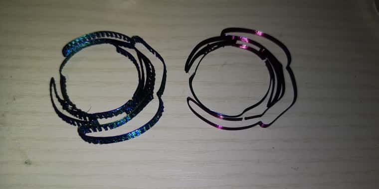
@leone Let me add the following:
below you will see a test model consisting of two connected half-circles, where the outer one is part of the original model, and the inner one was added by me as a part of a cylinder in order to compare.
Using firmware 3.5.4, the outer curve was printed with jerky movements, and the print was showing vertical ripples. In this case though the ripples were caused by the model itself, as it is coarsely facetted - you can even recognize the straight lines building the outer curve. I just disliked that the printhead was stuttering. On the other hand, the inner half-circle was printed smoothly, no matter which jerk values I used; its resolution was way higher. All in all, everything was printed as it should, with the exception of the apparent small stops at the junctions of the outer circle, which was causing jerky movements, but the half-circles were printed both OK.
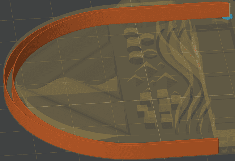
Now using 3.6.0-beta.4 firmware version, even the outer half-circle is printed smoothly! I mean, there are no jerky movements anymore, but what is more astonishing: the print itself shows no vertical ripples anymore!! (But it should, actually). It is printed as a perfect curve, although it is not! No facettes are recognizable at all. In other words, some kind of smoothing of the surface took place (but looking at the gcode, no arc fitting was applied). I would say, this firmware is "cheating", but in a positive way. The print was improved beyond any expectation.
Shouldn't that raise even some fidelity concern, I am asking myself now
Let me express the kudos that @dc42 and developers deserve. Version 3.6 is going to be a big throw indeed. I am perplexed.
@leone @gloomyandy @Notepad
I installed current beta version and am reporting my findings as promised.
After installation I got this message, which I surely can ignore for the time being:
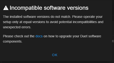
Let me anticipate that I repeated my problematic print using Version 3.6.0-beta.4.the result was:
Artifacts just disappeared, curved walls are printed smoothly even at low jerk values of 5 mm/s.
Look at this picture (it is just a horizontal section of the real model used as a test): Version 3.5.4 on the left, beta version on the right side:
It is an extreme case of vibrations that could be only partially mitigated by high jerk values. Other measures I took in my desperation (checking the toolhead, belts etc.) might have helped too, but no doubt - this firmware version is the solution.
@leone Now, just to learn, I would like to confirm that I understood how jerk is handled in this beta version.
If I set a jerk value, it will not always be applied 100%, as it represents a maximum value only. The actually used jerk will be calculated based on current speed and angle conditions of every two consecutive segments and will be smaller in most cases.
Accordingly, the jerk used in curves with wide radius composed of segments with same speed will be higher than the jerk used in similar curves with smaller radius, as the segments in the later ones are angled higher.
Jerk applied in square corners will be even smaller.
Cases where the direction is reversed will have a minimal jerk value (physically, the print head will come to a standstill at some point).
If all this is correct, from now on it should be considered a good practice to set a jerk value that is just high enough to cover all cases.
Correct me If I am wrong please.
A "special" case comes to my mind now, where segments are in a straight line - that happens when flow based acceleration/deceleration is defined in the slicer (this limits the flow change rate, but not based on movement speed alone). So here we often have consecutive segments that do not change direction, just speed. I assume then that if the speed difference is lower than the maximum jerk set, no jerk considerations apply, that is, the speed will change suddenly while trespassing the junction - but I am possibly wrong and steppers will always consider a junction to be a stop point, applying jerk. Feel free to say I have no notion about how steppers work.
Thanks so far.
@gloomyandy That implies that this thread, including your postings, are senseless.
Let me quote @leone :
"I am doing some motion tuning for a quite big and heavy machine. In general I noticed that having high values of jerk (about 500-600 mm/min) are good enough to travel circular paths smoothly (even tough it depends a lot on the mesh quality), but they are a bit high when printing corners"
This is what this whole discussion is about: Same jerk values don't fit well in corners AND curves, and should be made adaptive. This is exactly my concern, as I explained. You can read the details above.
So I cannot follow.
@gloomyandy The angle dependent jerk.
@gloomyandy I have to believe you, anything else would be my blatant arrogance. At the same time, my experience with the firmware release 3.5.4 fails to confirm that.
The resolution of this contradiction is simple. I will install that beta version right now. I will let you know the outcome.
May I assume then that the feature as you described it will be in the next stable (official) release?
@gloomyandy Gotcha. Let's hope @dc42 or @T3P3Tony are reading this.
I will try the last beta and report. But I would rather avoid resonance vibrations by fighting their cause in the first place, better than trying to compensate them.
It is my understanding that junction deviation takes the angle of movement change into account in order to calculate and apply the jerk value, and RRF does not do that. For me, that is an essential difference (caveat: I am not very familiar with Klipper, I just try to assess its advantages).
@gloomyandy Perhaps you are drawing wrong conclusions from lack of participation of other developers. Some of them modify the firmware for their particular interests, so they just do their own thing and don't care (my speculation).
In any case, mortal users would definitely welcome that kind of adaptive jerk.
Let me try to emphasize. I don't know how to explain my point. Haven't you noticed? Half a world of 3d printing people is talking about things like pressure advance, retraction, flow, speed and acceleration - the key elements to control for a succesfull print. With junction deviation (or something similar) one more advanced mechanism would enable to get rid of defects commonly found everywhere.
Klipper is becoming overwhelmingly popular and is considered the firmware of choice for ambitioned users, but every time I check and compare to RRF I have come to the same conclusion: no reason to switch, and RRF is more polished and reliable.
Until now. Why this adaptive jerk has not been done after years of RRF development... I can't understand. In my naivity, I was even asuming there is some gcode command to tune that, but no.
In my particular case, my prints tend to come out flawlessly, except I get caught by the jerk dilemma. Either low jerk and jerky, stuttering curves with artifacts , or high jerk with smooth, uniform curves but visible ringing around corners. I am constantly changing jerk settings, depending on whether the model has many corners or many curves... Seems not acceptable to me after the underlying factors have been clearly understood. Roughly: Next segment moving in same direction? High jerk! Otherwise: Low jerk! That is not rocket science.
So again, the impact of this feature is not trivial. It is not just "nice to have" but a plain necessity.
Sorry if I my statements are too blunt.
Right now we can see how a certain proprietary printer brand allows itself to treat their clients as slaves, but only because they did many things just right and conquered the market. Open systems, to which Duet3d belongs, can and should perform better.
I said what I said. Let's paint the town red.
@Notepad I am using last stable version from Dec. 2024 (I think it was December).
Yes I will jump into the beta version. I read that the modulation of nozzle temperature depending on flow has been implemented. I have been doing experiments with varying temperature during the print using a postprocessor script and believe me, that is a great feature.
But I will have to update the PanelDue firmware first.
@gloomyandy May I ask what has been already implemented, today 6 months later?
I am not asking out of mere curiosity. I am struggling with jerk values that are low enough at square corners (in order to avoid ringing) but are at the same time high enough to allow printing smooth curves. A kind of adaptive jerk would be the obvious solution (depending on the angle and speed difference between every two consecutive segments). Call it junction deviation if you like.
@stuartofmt I am looking at different options and learned about a switch with a ESP8266 NodeMCU microprocessor, which is more elegant and flexible. It runs a Webserver as well.
If you are interested:
ESP8266 Button
@stuartofmt I just read that discussion, looks a bit chaotic but the hint about the BTT Supercap UPS is valuable.
@T3P3Tony Thanks!
I just wanted to clarify that it is really not necessary to build a pack of supercaps yourself. I was looking around and found some solutions. Often, supercap modules are offered to be used in automotive applications to protect the vehicle battery from to sudden current surge or to stabilize board voltage to satisfy hifi equipment (music listening people tend to be very demanding when it comes to sound quality).
For example, this one:
5PCS 1Set Super Capacitor 13.5V 12F Single Row Farad Capacitor2.7V 60F Automotive Super Farad Capacitor Module Supply Rectifier
Of course this would only be suitable for a 12V power supply, but you can connect two of them in series. This boards have voltage protection and balancing built-in. They are even oversized for this case (remember: the purpose is to allow a controlled shutdown, not to run the printer on UPS).
For more ambitious people, a 24V module is also available, for about $100 on Amazon, or around $21 on AliExpress:
GDCPH 24V5.5F Supercapacitor Electronic Rectifier Module 2.7V50F Super Farad Capacitor Backup Power Supply 24.3V Electrolysis
Note that it is composed of 9x50F supercaps in series (resulting in 5.5F), which is plenty of energy.
Still, these are not full fledged UPS - you still need the combo of resistor and Shottky (in parallel to each other) between the module and the PSU.
I even found a supercap module exactly as @dc42 proposed, if using two of them in series:
[16V 1F/2F Farad Capacitor Module 2.7V 10F Super Capacitors With Protection Board]
(https://www.aliexpress.com/item/1005002715223142.html)
You get one module for $6 or two for about $12, fairly affordable. That is currently my preferred option. The BigTreeTech 24V UPS mentioned above does not add any value because the Duet already has a power failure detection built-in.
My impression is that supercap based UPS are becoming popular. There are some professional solutions, for example customized for a Raspberry Pi (if you use one):
Andino-UPS - Supercapacitor UPS for the Raspberry Pi
but I also found some DIY projects. They should be considered as "emergency power supply" rather than UPS due to the limited length of time they can keep a printer running.
Engaging in this matter I have some new questions and ideas, namely: I would like to switch my printer on remotely (it is in an attic and I always have to go upstairs to switch it on) - a reversed question in comparison.
But also: What happens when I just switch the printer off in a regular manner when resurrection has been configured? The voltage will drop to the defined threshold in this situation too- will then the power failure procedure defined by M911 be executed? I have never checked that. OK, as a rule, no print job is running when I deliberately switch my printer off, so I suppose the procedure is only triggered in this case.
Why I come up with this question?
Assume that I have a small UPS that is able to detect failure of the mains power. It does not have to wait until DC voltage drops below say 22.5V to kick in. I can then save current coordinates and take some other precautions to prepare the resurrection, even before the voltage threshold is reached. Will then the power failure procedure defined with M911 still be executed a 2nd time when the DC voltage falls?
A real UPS has one key advantage compared to an emergency power supply, even when it is not meant to run the printer accross the powerless time, since it allows to keep the hotend fan running for a couple of minutes until the hotend gets cold enough, so to avoid nozzle clogging. In this case, the question whether M911 kicks in and saves the current state a 2nd time would be relevant.
I am done.
Thanks again.
@dc42 I wanted to wrap up some informations about this topic but found that I am not allowed to post links - I need two "reputations".
That's a pity. Would anyone be so kind to enable posting links for me? At least for this time. (Assuming that my findings are of general interest for the furure).
@dc42 Of course! Why didn't I myself come to the idea of combining several capacitors, so having even more design flexibility.
You gave me the decisive impulse to start this task. I would even use the remaining power to run the hotend fan a bit longer to avoid nozzle clogging after a sudden heater shutoff.
By the way: What I most appreciate using Duet hardware is... this help forum, definitely (beside their indisputable quality). Sincere thanks!