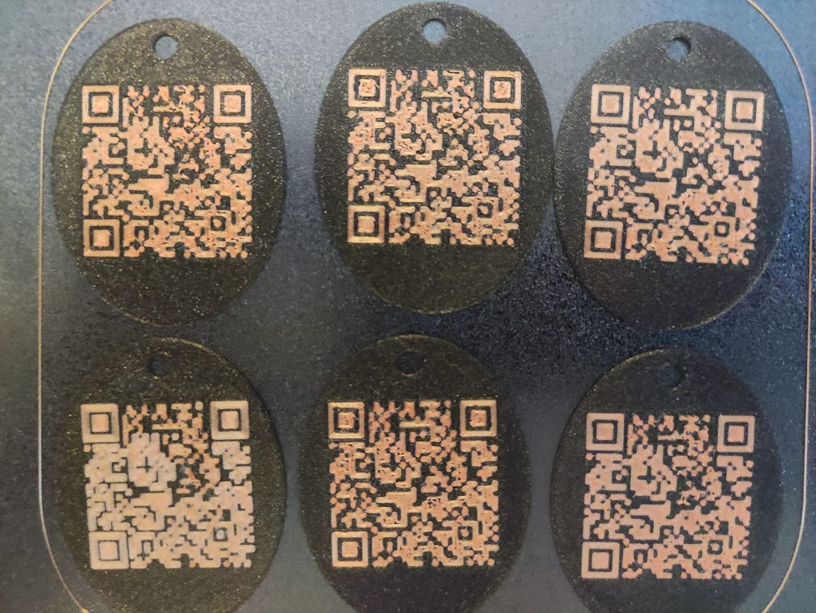
One thing I am wondering. When you guys say that you always get a perfect first layer and don't understand why it doesn't work for me, do we mean the same thing? That means, can you level your nozzle to the bed so that at its G31 value, it is set to z 0 (=touching the bed without a paper in between) and then always print a perfect layer on a bed (that has a bad of about .5 deviance or so), without using a z probe offset (ie with m290 at 0 and not changing G31)?
Because my problem is not that i am not able to squish irregularities out of the first layer with a negative z probe offset, the problem is that with a negative z offset, the first layer does not perfectly maintain the extrusion width, which negatively affects the QR Code embedded into the first layer. Which I believe is probably a major difference. I got the impression, that on a bed with more than .1mm deviation, you can not perfectly maintain the extrusion width on the first layer of a print with multiple colors on the first layer.
@engikeneer said in Mesh Compensation Overcompensating a bit?:
@suntoxx a couple of extra thoughts for you from my experiences with mesh comp...
First obvious question is have you double checked that mesh compensation is active during the print? I appreciate its a silly question, but a stray M561 has sent me nuts before...
Yes, it's working. Only got M561 in my leveling macro and and got G29 in my startcode.
What is your min z height allowed in config? You'll need to allow a small negative amount so that it can reach the low points on your bed.
I have tried down to -4, but various first layer prints showed no difference between 0, -2 and -4. Would't it be a strange thing if the programmers allowed the mesh compensation to end at 0, when most of its job is to compensate below 0?
Have you checked that the BLTouch trigger height is consistent across the bed? Could be that any small gantry sag/tilt could be affecting it in some areas? Even just the eight of the wiring and filament feed could flex things a few micron. One option for testing this is to manually edit a heightmap in excel to make it compensate more in the areas you are seeing issues. There's a couple of bed levelling stls on thingiverse that work quite well for this kind of thing
I believe this shouldnt be a problem. It is a CaribouDuet with 10mm Misumi rods, carriage has LHBB10 aluminium bearing blocks and Igus energy chains. Printer came preassembled and calibrated.
Also, there are no signs of tolerances. If I optimize somethingto print in one place of the bed, it reproduces it there without any variance.
However, as some of the keychains themselves, when copied around the bed, seem fairly consistent, an offset for each of them might actually improve the performance of the mesh compensation, I believe. But manually editing the heigtmap won't proof that the printer is at fault, will it?
 I have done quite a bit of testing and can't seem to find any confirmation of this working. Is there any documentation about this or has one of the responsible coders mentioned this? (is this compensation reprap oder duet3d code?)


