Just wanted to mentin after I got a replacements for the heater core it prints as expected again. Now I measure within 5C at 100C.
Posts made by strips
-
RE: Wrong measured temperature on nozzle, suggestions?posted in Duet Hardware and wiring
-
RE: Wrong measured temperature on nozzle, suggestions?posted in Duet Hardware and wiring
Did some measurements last night. I managed to push my glass-bead temp probe in between the silicone sock with some heat sink compound so it should have a pretty good contact point to the Revo core. I took my hot air station and funnelled hot air over and through the core.
25°C measures about 100 kohm as expected.
99°C measured 5.3 kohm (expected 6,37 kohm)
250°C measured 172 ohm (expected 227,8 ohm) (RRF calc. B4566 C3.492687e-8 )
248°C measured 163 ohm after >5 minutes with heat@250°C. I could also watch that the resistance slowly drifts lower even the temperature is stable or drops a couple of degrees.
262°C measured 133 ohm (RRF calc. B4719 C5.809083e-8 )All these measurements ware done in one go, I never turend off the heat in between. The resistance drift kind of worries me. I swapped out the multimeter and both measured the same resistance.
I also verified that my measuring probe is dead on the temperatures at 100°C, 200°C and 260°C in my kitchen oven.
So I'm relatively sure something is wrong with the thermistor or E3D used/sourced the wrong ones. They told me "The Thermistor type used on the Creality hotend is a EPCOS 100K B57560G104F." and it has the yellow wrapped wires. So I'll see if I can get a replacement from them. Maybe wait till I can get a 104GT-version instead.

-
RE: Wrong measured temperature on nozzle, suggestions?posted in Duet Hardware and wiring
Hmm.. I do have cheap Chinese soldering and hot air station. Have no clue how precise and stable temperatures it can give me. See if I can dig it out and maybe I have a tip I can thread into the revo core or use the hot air while clamping the temp probe to it.
I'll see if I can get some measurements with it.
-
RE: Wrong measured temperature on nozzle, suggestions?posted in Duet Hardware and wiring
Redoing my last test last week.
Before turning on the heater for the day I verified it measures room temperature. It shows the same as my measuring probe and bed so it measures correct room temperature (23C).
220 ohm resistor gives 252 degC with the following
M308 S1 P"e0temp" Y"thermistor" L-75 T100000 B4092Turning on the heater to 100C and my probe shows 81C stable after several minutes. I also added a generous dollop of heat sink compound
like @mrehorstdmd suggested. As it's pressed against the nozzle bottom flat (not the tip) with a wad of paper tissue it should stabilise to something pretty close to the actual nozzle temp.M308 S1 Sensor 1 type Thermistor using pin e0temp, reading 100.0, last error: sensor open circuit, T:100000.0 B:4092.0 C:0.00e+0 R:4700.0 L:-75 H:0 -
RE: Wrong measured temperature on nozzle, suggestions?posted in Duet Hardware and wiring
I just tested a 220 ohm resistor for the Low values and I need L-75 to get a reading of 252 degC.
I'll tried this line now
M308 S1 P"e0temp" Y"thermistor" L-75 T100000 B4092Room temp was correct
Target temp on Duet 100C resulted in 75C measured by my meter.Yesterday I verified my own meter on boiling water and it showed 100C so it's good.
@dc42 I could put the whole heater core assy in my oven but don't think I should go above 100C. The connectors might melt

-
RE: Wrong measured temperature on nozzle, suggestions?posted in Duet Hardware and wiring
@dc42 I'm struggling to see how I can do this. I do not have any way to heat up the sensor to a precise true and known temperature. And while the sensors are in use on the Duet I'm not able to measure the resistance by it self.
-
RE: Wrong measured temperature on nozzle, suggestions?posted in Duet Hardware and wiring
@dc42 with B4092 it shows the same as the bed which is pretty close to the room temp. 24C.
So might just do the low offset calibration?
-
Wrong measured temperature on nozzle, suggestions?posted in Duet Hardware and wiring
Hi,
I have an issue with the sensed temperature on a new replacement E3D heater core. My local shop did not have the core with the regular GT104 so I bought one with the "Creality"-thermistor. According to E3D it's a EPCOS 100K B57560G104F.
Now I have tried what I thought was correct settings and some. I have a measuring probe (glass bead on a meter) pushed against the bottom flat of the nozzle. A thick wad of paper towel is pushing it against the nozzle. The paper also insulates, and I should get a relatively good measurement. To verify my probe I also just measured my bed with the same method and it's spot on after settling.
Setting the Duet 2 to 100 degC with the following configs I get these values:
;M308 S1 P"e0temp" Y"thermistor" T100000 B4725 C7.06e-8 ; measures 92 degC
;M308 S1 P"e0temp" Y"thermistor" T100000 B4092 ; measures 89C
;M308 S1 P"e0temp" Y"thermistor" T100000 B4072 ; measures 88C
;M308 S1 P"e0temp" Y"thermistor" T100000 B3950 ; measures 75CI believe B4092 is the correct value here but 12C difference at 100C is not good.
Anyone have a suggestion here? My next step is to do a manual calibration on my Duet 2 Ethernet.
I found a 222 ohm resistor but can not find one with more than 10k for the high offset. 10k is about 85C so it's not ideal.
Regards
Stian -
RE: Rounded corners with Pressure Advanceposted in Tuning and tweaking
Thanks! That sounds sensible.
-
RE: Rounded corners with Pressure Advanceposted in Tuning and tweaking
Thanks. Since you often need less retraction when using PA, I thought to do an initial PA calibration without any retraction. Then calibrate retraction and eventually a new PA calibration to see if it changes in any way.
I usually have retraction set between 0.2 - 0.4, so it's not a lot anyways.
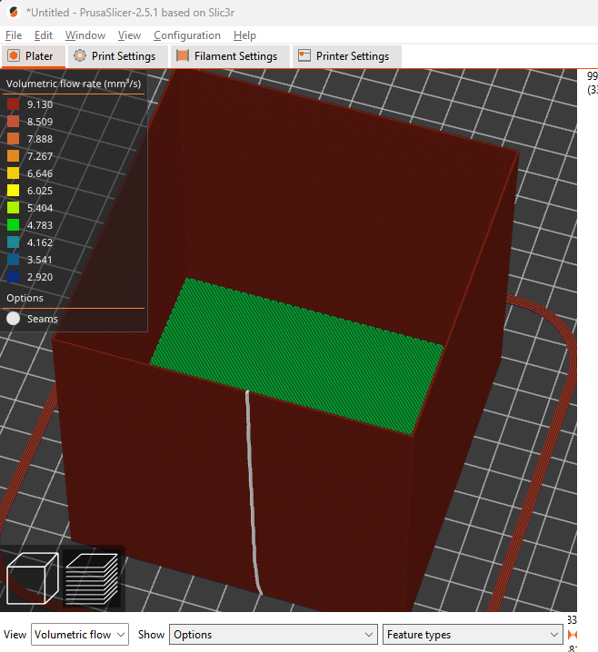
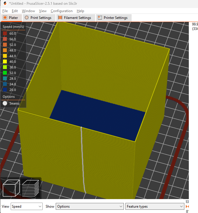
In reality I have a constant speed of 40mm/s in all moves in the test which coincidently gives me a constant flow with only a single wall. At least according to speed and volumetric view in Prusaslicer.
-
Rounded corners with Pressure Advanceposted in Tuning and tweaking
Hi,
I could use some suggestions on where to go from here.
Decided to try calibrate a new 0.8 Revo nozzle with PETG. I have been printing a 100x100x100mm cube with a single wall and no infill or top layers. I set the seam in the middle of the wall along the x-axis (towards the front of the printer).
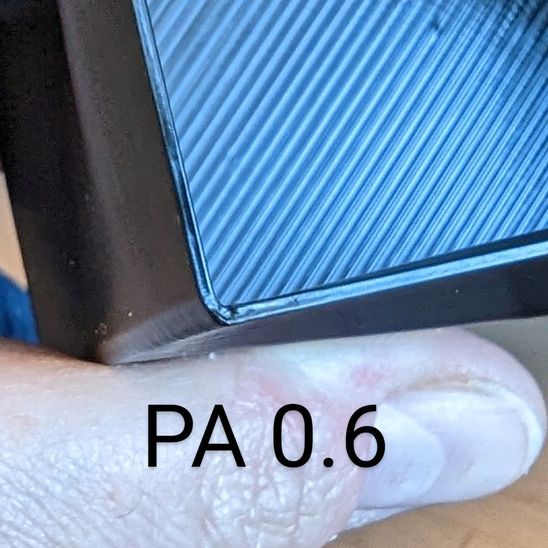
PA = 0, I get a bulge in the seam. The corners look pretty ok, maybe a slight bulge.
PA = 0.06 the seam is the prettiest, but now I got strangely rounded corners. Like they are being cut of too early.In between 0 and 0.06 I have to choose between rounded corners or bulge in seam. The inside corners look ok.
I did two tests with different acceleration and jerk increasing. Tested acceleration between 100 and 1300 and jerk between 150 and 2000 but nothing changed much, just slightly. 40mm/s is probably to slow to show much of a difference.
Could it be low quality PETG?
I'm levitating towards having crisp corners and having to live with a bulging seam.- Ender 5 Plus
- Hemera direct drive with Revo 0.8mm nozzle
- Volumetric flow for is constant ~9mm3/s for whole print
- Speed 40mm/s
- 0.3mm layer height
- 0.87 mm width
- All retraction has been disabled for tests
M203 X15000 Y15000 Z1200 E3600              ; Speed - set maximum speeds (mm/min)
M201 X500.00 Y500.00 Z100.00 E1000.00       ; Accelerations (mm/s^2)
M566 X900 Y900 Z60 E3000                    ; Jerk -  gammel. brukt en stund nå
Any suggestions?


-
RE: Bug? In Retraction and Movement Junctionposted in General Discussion
Anyone still has this issue? Was there a resolution? I might have something similar but I'm still testing.
How about you @jatmn?
-
RE: XYZ-cube with a pre-shadow?posted in Tuning and tweaking
Thank you very much @mwolter. I have a lot better prints now.
These prints where printed with the new cooling fan shroud. The temp tower in the photos are all printed at 235C but the fan increases 10% for every block. Bottom level is no fan and the upper is 100%. 10% - 20% seems a good value.
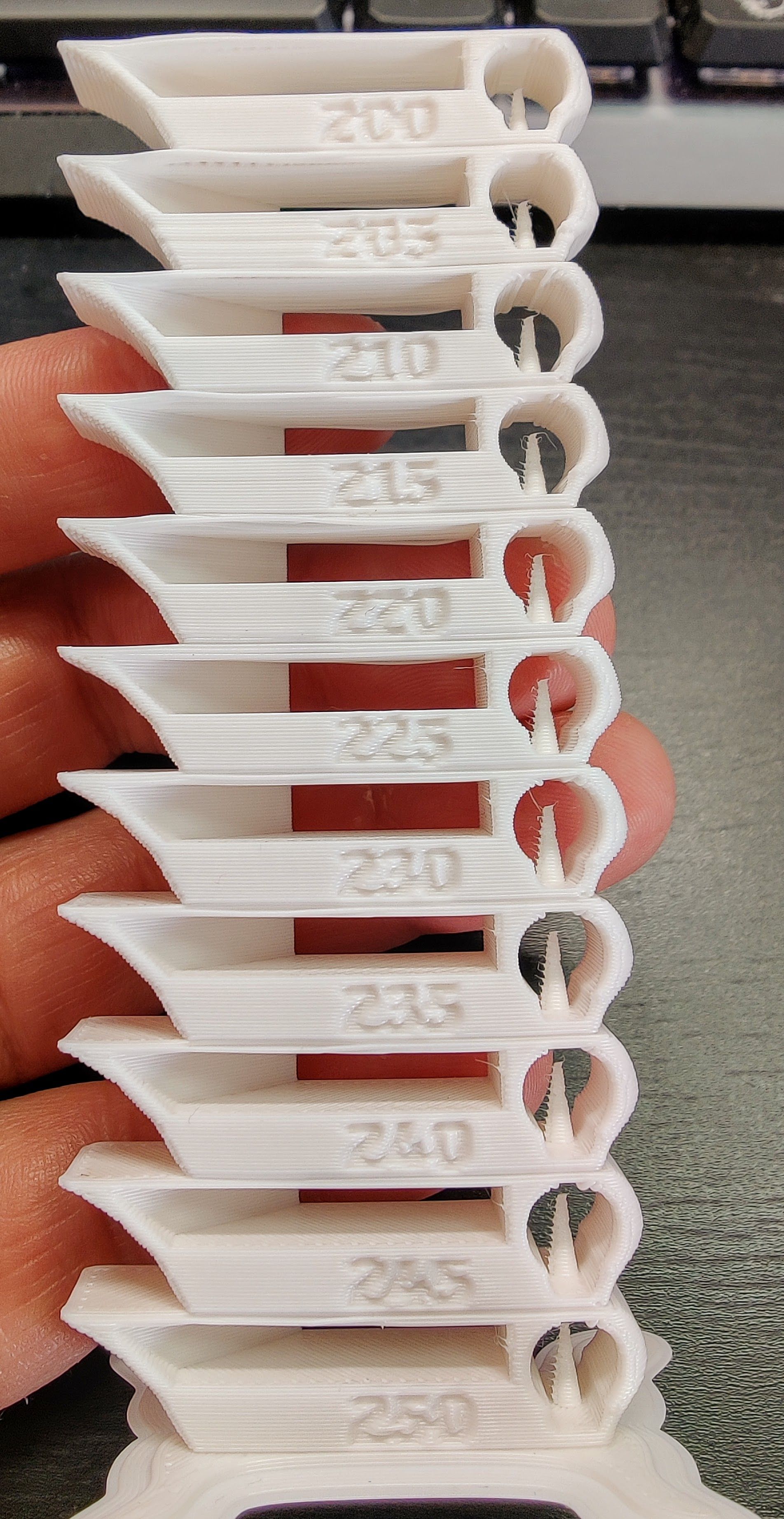

Seems like slight under extrusion but overall this part is almost perfect. Printed at 235C and 30% fan


-
RE: XYZ-cube with a pre-shadow?posted in Tuning and tweaking
I hope to be able to print a fan shroud now to enable me to print a better fan shroud

Made some technical parts and some are very good but some are bad. So next issue is cooling.
I did not believe ABS wanted cooling? Is there a way to only start fan when there are overhangs in S3D? There is a bridging option to use fan.
-
RE: XYZ-cube with a pre-shadow?posted in Tuning and tweaking
I made two more runs with single wall boxes and expecting 0.5mm wall I get an average of 0.495. Almost 50/50 measurements of 0.49 and 0.5mm. The last was at 220degC and it's too easy to delaminate the walls but it looks pretty perfect!
I made an temp-tower to show the effects of changing temp. It's surprisingly forgiving in a large range. Or maybe it sucks at just about any temp
 Need to buy another brand to test.
In my opinion it's the best temp-tower I have made so far. Bridging and steep overhangs are not very good. I have no enclosure but a very small room that gets about 40degC. I have no functioning cooling fan at the moment as well.
My goal is to make solid parts with good geometry for the printer it self. They do not have to look perfect but of course I want them too look as good as possible with the limitations. I want to use ABS to better withstand an future enclosure.
Trying to break the tower 215C broke very easily. Then 230C snapped with a bit more resistance but still easily delaminated. 240 required more force and 245 was much more solid. Not a very scientific test but confirms earlier observations that below 230 the layers do not bond properly. To avoid delamination for thin high parts I need to keep it above 230, preferably 240-245. I am not able to see much improvement below 240 anyways.
Lowest block is printed at 250 and lowering 5C every block above.
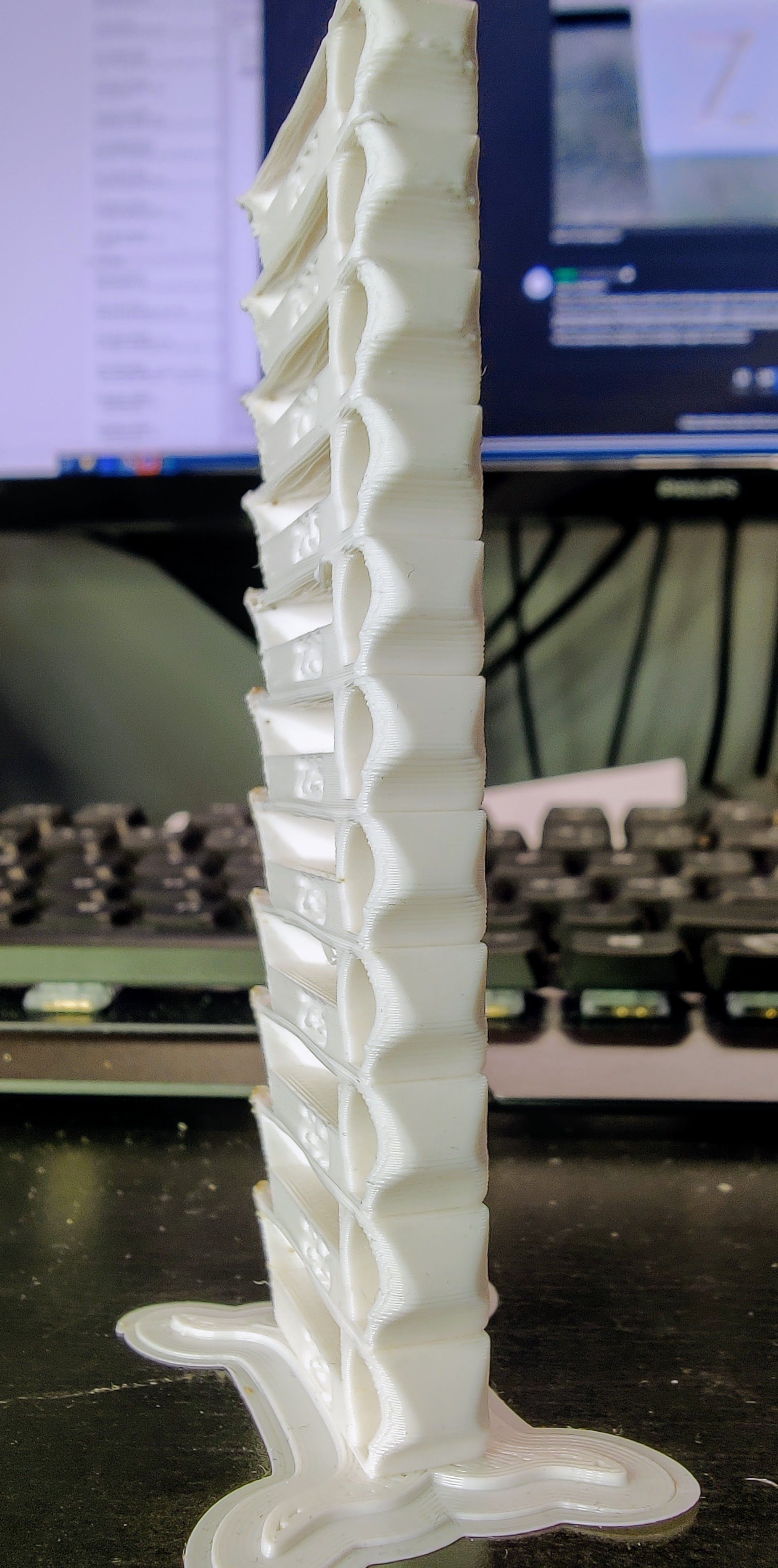
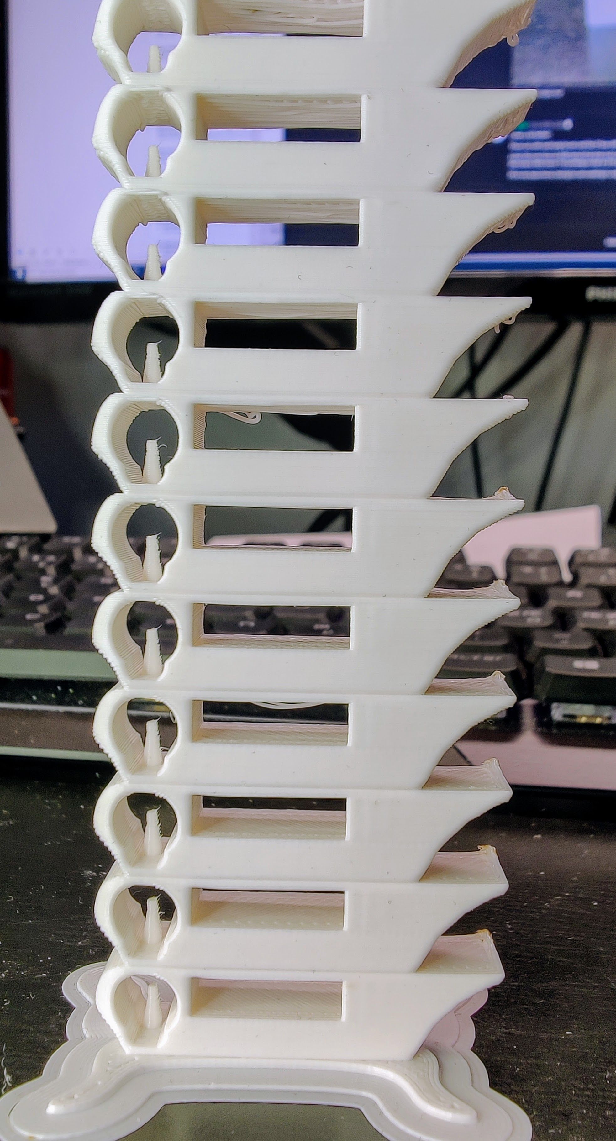
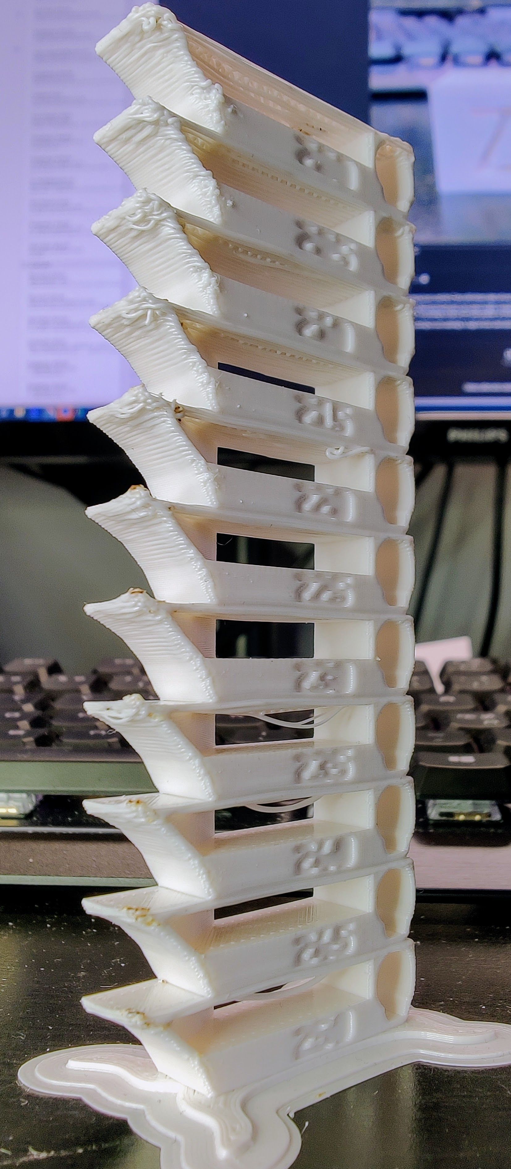

-
RE: XYZ-cube with a pre-shadow?posted in Tuning and tweaking
Looks a lot better but the Y-side overhang looks a lot worse than the X. Z top surface looks pretty good. Again, it looks a lot better in real life as I try to show off any imperfections with the lighting.
Changes:
- Extrusion 87%
- Temp to 220degC
- 0.1mm coasting


-
RE: XYZ-cube with a pre-shadow?posted in Tuning and tweaking
To check my extrusion I printed two 30x30x30 boxes. One with 4 layer outline and one with a single layer outline. Both with 0.5mm width.
I sampled the walls 4 times on each side. The single wall is slightly wider but the 4 walls is barely measurable.
Any suggestions which measurement I should weight the most?
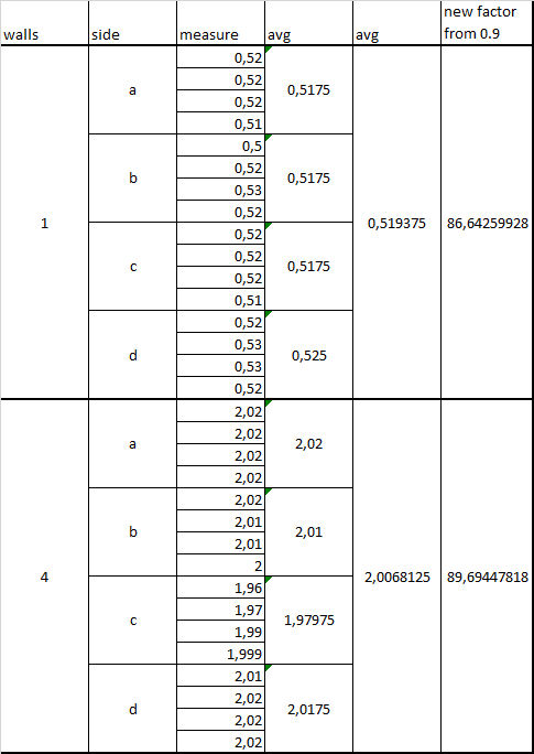
I think I have put too much pressure on the calliper on earlier tests. I get slightly longer measurements when I only press the part of the calliper where it actually measures. Maybe spend a bit more on a sturdier one.
-
RE: XYZ-cube with a pre-shadow?posted in Tuning and tweaking
Strange stuff.
I have tried lots of combinations of high and very low jerk and acceleration. I have tested most combinations with PA from 0 to 1. I have tested Prusaslicer in addition to Simplify3D and I still get the strange line/shadow before a corner.
I went through the mechanics and re-"trammed" the printer. Adjusted all the v-slot wheels and retightening belts. Still no help.
So I'm beginning to think it's the filament that just get pulled like that in a corner. I would believe that this could be improved by temperature and speed but no. Tested the ABS between 215 - 250. Below 230 I get worse layer adhesion so I tend to print 230-240.
So I ditched the single wall tests. I have printed some XYZ-cubes in default size 20x20x20mm that actually doesn't show the line/shadow very much. Looks like some over extrusion but else not bad.
0.4mm nozzle
Layer height: 0.28
width 0.5
extrusion Multiplier 0.9
Retraction 0.35
topSolidLayers 3
perimeterOutlines 4
infillPercentage 90
temperature 240
bed 110
fanSpeeds 0Pressure advance 0.01, 0.025, 0.035 and 0.05


Please disregard the bottom layers. Seems I need to recalibrate the z probe offset

-
RE: XYZ-cube with a pre-shadow?posted in Tuning and tweaking
Are there any settings that could help me pinpoint any mechanical problems?
Like stupid slow printing that should work with any rubbish mechanics or increasing stress to provoke the issue further?
-
RE: XYZ-cube with a pre-shadow?posted in Tuning and tweaking
I've been considering that my self but not sure what to look for. It's a brand new E3D Hemera with a printed carriage. I ditched the metal plate and the v-slot wheels are mounted directly in the print. Seems just tight enough. I have the issue in both X and Y axis. So that makes me believe its something with the extruder. What could make it drop pressure before a sharp corner?