Hi, is it possible to correct for a temperature offset between the hotend sensor reading and the actual temperature within the nozzle via gcode? In this case I would need to give it a slope of 2.75 minus 54°C (y=x*2.75-54) to correct a reading of 100°C for an actual temperature of 218,5°C (yes that is huge but it cannot be helped hardware wise currently).
thx!
Best posts made by stellator
-
Thermocouple temperature offsetposted in Firmware wishlist
Latest posts made by stellator
-
RE: CoreXY with four motors (AWD)posted in Duet Hardware and wiring
Okay, putting the kinematics definition M669 k1 in front of the driver definition helped in that sense that I can now use 4 out of 8 different direction settings for the four motors (which is in line with my expectation because two motors need to be paired always) instead of only one as was the case before (every other combination resulted in stalling motors).
However, following: https://docs.duet3d.com/en/User_manual/Machine_configuration/Configuration_coreXY#testing-motor-movement again, I can either swap the directions/polarities of both X and Y axis at the same time or I can swap X for Y but I cannot keep X and Y correct and only change the Y polarity as needed, for my Y endstop is at the high end and the tested heightmap (and hence the future print) is mirrored in Y.
Also, its strange that changing the endstop config from high to low does not affect the direction of the homing move as I would expect (but thats maybe due to the formula I copied from the RepRap configurator:
var xTravel = move.axes[0].max - move.axes[0].min + 5 ; calculate how far X can travel plus 5mm
var yTravel = move.axes[1].max - move.axes[1].min + 5 ; calculate how far Y can travel plus 5mmI also did put the motors at different ports and tried the same thing again but with the same result, as expected.
Out of ideas right now, or is it because of the four wheel drive Iam using (AWD, four motors, Voron or whatever is the correct synonym for it)?
-
RE: CoreXY with four motors (AWD)posted in Duet Hardware and wiring
@o_lampe Thats a good idea! I will try and report..
-
CoreXY with four motors (AWD)posted in Duet Hardware and wiring
I just found that the Y axis on my new coreXY is inverted when I was doing my first heightmap measurement (which wasnt all to straight at all).
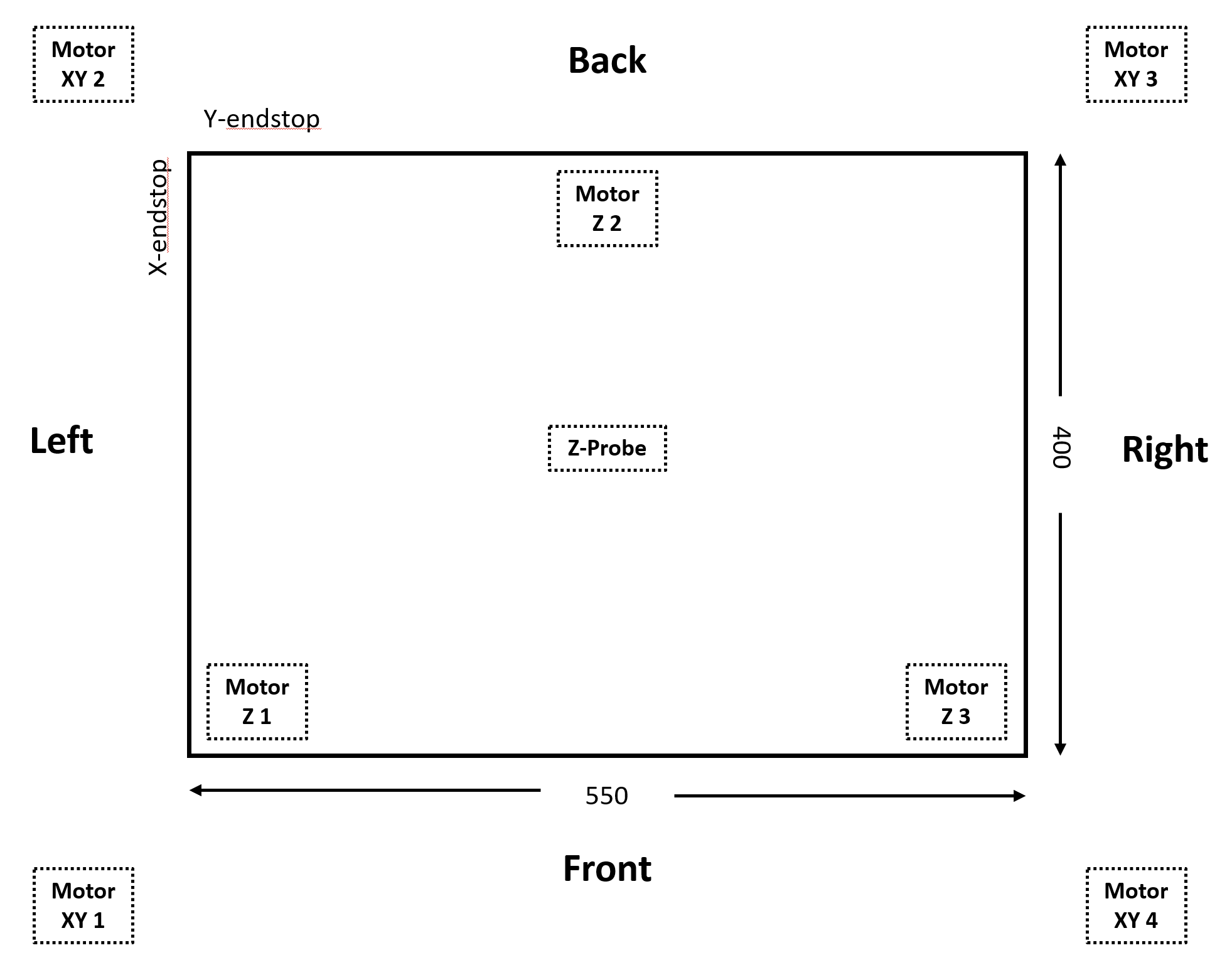
Looking at the printer from the top, my endstops are at the back left side instead of the front left side as expected per default of RRF.

I have tried all possible configurations of drivers going backwards or forward and endstop being at the min or max end but there is only one configuration that works with all the motor operating in tandem and not against each other but in that configuration the Y axis is flipped relative to the RRF coordinate system.
Wiring (for cable length reasons):
Motor XY 1 goes to Duet2Wifi E0-Stepper
Motor XY 2 goes to Duet2Wifi Y-Stepper
Motor XY 3 goes to Duet2Wifi E1-Stepper
Motor XY 4 goes to Duet2Wifi X-StepperPlease find my configuration below, do I really have to swap motors on the controller board in order to get orientation right as I understand from some posts?
; Axes
M584 X0.1:0.3 Y0.0:0.4 Z0.5:0.6:0.7 ; set axis mapping
M350 X16 Y16 Z16 I1 ; configure microstepping with interpolation
M906 X2200:2200 Y2200:2200 Z800 ; set axis driver currents
M92 X80 Y80 Z1600 ; configure steps per mm
M208 X0:550 Y0:400 Z0:400 ; set minimum and maximum axis limits
M566 X5000 Y2000 Z100 ; set maximum instantaneous speed changes (mm/min)
M203 X10000 Y80000 Z1500 ; set maximum speeds (mm/min)
M201 X10000 Y6000 Z100 ; set accelerations (mm/s^2); Extruders
M584 E0.2 ; set extruder mapping
M350 E16 I1 ; configure microstepping with interpolation
M906 E1000 ; set extruder driver currents
M92 E420 ; configure steps per mm
M566 E120 ; set maximum instantaneous speed changes (mm/min)
M203 E3600 ; set maximum speeds (mm/min)
M201 E250 ; set accelerations (mm/s^2); Kinematics
M669 K1 ; configure CoreXY kinematics; Endstops
M574 X1 P"xstop" S1 ; configure X axis endstop
M574 Y1 P"ystop" S1 ; configure Y axis endstop; Probes
M558 K0 P1 C"zprobe.in" H5 F120 T6000 ; configure analog probe via slot #0
G31 P200 X0 Y-20 Z0.5 ; set Z probe trigger value, offset and trigger height
M574 Z1 S2 ; Set Z endstop probe
M671 X-38:275:588 Y365:-100:365 S10 ; Z pivot points are at (-15,220), (100,-20) and (215,220); Mesh Bed Compensation
M557 X25:525 Y25:375 S80:80 ; define grid for mesh bed compensation -
RE: LED stripe does not light up after firmware updateposted in General Discussion
Thanks for your replies, I did not understand from the documentation, that those names like "duex.fan4" etc. are the definitions nowerdays that have to be used rather than just names I can freely choose because in older firmware versions they were defined by M950 P6 e.g.. which was more straight forward than to have to know the dedicated name that allows for even more typos.
I did not stumble across any list that gives me all the RFF 3.5 "names" of all the ports that are available on Duet2wifi / Duex5 in the documentation but I was sure lasy.However, this is how it works for me now in RFF 3.5x (for both fans and LEDs)
M950 F4 C"duex.fan4" Q500 ;
M950 F5 C"duex.fan5" Q500 ;
M950 F6 C"duex.fan6" Q500 ;
M950 F7 C"duex.fan7" Q500 ;And this was the way back then in RFF 2.xx or such:
; Fans
M106 P3 S255 ; Cooling fan
M106 P4 S100 L515 B2 R100 ; Hotend fan 4 Thermostatic control to turned on at 50C of Heaters 1 or 2
M106 P5 S0.9 ; Green LED to 30% power
M106 P6 S0.9 ; Blue LED to 30% power
M106 P7 S0.9 ; Red LED to 30% powerBut I very much appreciate all those new options you can do in RFF 3.5 so an equivalent amount of complexity is the price one has to pay..
-
RE: LED stripe does not light up after firmware updateposted in General Discussion
@dc42
Many thanks for your fast response!!So I just tried
M950 P8 C"duex.fan8" Q500 ;
M42 P8 S1 ;and
M950 F8 C"duex.fan8" Q500 ;
M106 P8 S1 ;Both didnt work (I also doublechecked that both my fan and the led stripe work, using my lab power supply)..
-
LED stripe does not light up after firmware updateposted in General Discussion
I somehow totally forgot that configuring the firmware is, by far, the hardest part of building a 3D printer from the scratch

I had a LED stripe up and running in my previous printer using the Duex5 fan ports 5,6,7, using this code, plain and simple (without even using m950 command) in firmware 2.0X:
; Fans
M106 P3 S255 ; Cooling fan
M106 P4 S100 L515 B2 R100 ; Hotend fan 4 Thermostatic control to turned on at 100C
M106 P5 S0.9 ; Green LED to 90% power
M106 P6 S0.9 ; Blue LED to 90% power
M106 P7 S0.9 ; Red LED to 90% powerAfter sequential and successfull updating to 3.52 I cannot bring them back to live (they briefly flash upon startup) and I fear I cannot find the information I am missing about how to configure M950 and M106 correctly. Lastly I tried
; LEDs
M950 P8 C"duex.fan8" Q500 ;
M106 P8 S0.9 ; Red LED to 90% poweramongst many other parameters (I found in the documentation but with all the firm-, hard- and software combinations available these days its getting weired and I am afraid not 100% fool proof anymore) but to no success. Does anybody have a functinoal code based on firmware 3.5X? Many thanks!
-
RE: Additional stepper drivers on Duex 5posted in Duet Hardware and wiring
Hi again, Iam building a new printer using Duet 3 mini 5+ instead of my old Duet 2 wifi.
I like to use the external 5 phase oriental motors again but I find that the Duet 3 mini 5+ only has one "enable" Pin for the "external drivers". I might be lucky since its going to be a core xy so both A and B motors want to be enabled simulatneously at all times but am I correct assuming that Pin 16 is meant to be used as a shared enable Pin - does it work that way?PS: IS there any easy way to give the Step, Dir, En, signal 5V instead of 3.3V on the Duet 3 mini 5+ (Because one stepper driver is working correctly whilst, when swapping cables, the other driver does not change motor direction although DIP settings are identical. Adding to the confusion, only motor pins 12, 13, 15 assigned as motor 0.6 are functional when using pins 4, 5, 7 assigned as motor 0.5 nothing is moving?! So I speculate that I might be just at the edge of signal detection using 3.3V instead of the recommended 5V-24V resulting in this erratic behaviour?
PPS: Read some posts and manuals meanwhile, seeing that it shopuld be possible to get 5V but is it necessary..?
-
RE: automatic 3 axis bed levelling: kinematic versus maxwell mountposted in My Duet controlled machine
Thanks for your quick replies!!
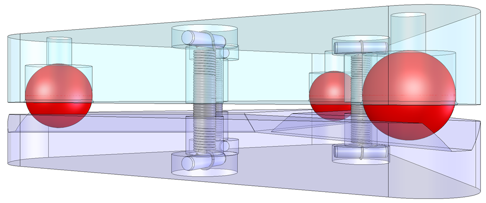
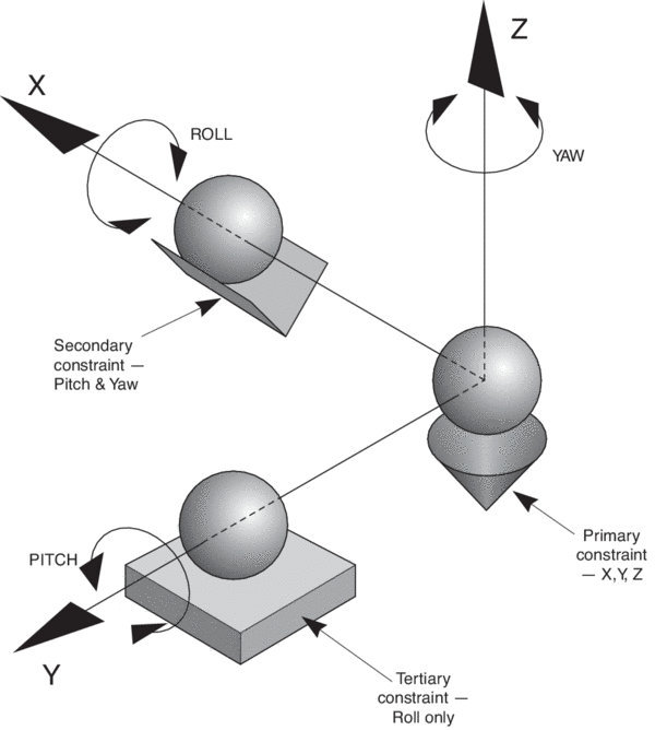
And I am glad to hear that the firmware can cope with any geometry as long as I can provide the correct coordinates!Also I decided to not go for the first version (image 1) but for the maxwell design (image 2) because then the printbed will tilt around the center of the triangle instead of the middle rear axis. I expect any future firmware that might support tilting the bed whilst printing to operate with the center of rotation be equal to the center of the coordinate system X=0 Y=0, at least that would result in the biggest possible print area in a tilting bed scenario. So yes, its intended be "tiltbed ready"

Now lets see how to actually home a core xy and soon it might come alive: Turn both motors in one direction until Y endstop is triggered and then rotate both in opposite directions until X is triggered? Hmm - that should do it...

-
RE: automatic 3 axis bed levelling: kinematic versus maxwell mountposted in My Duet controlled machine
@stellator Maxwell clamp as reffered to a way of 3 axis print bed levelling

-
automatic 3 axis bed levelling: kinematic versus maxwell mountposted in My Duet controlled machine
Hi Zusammen, I hope I dont mix up the terms here but nevertheless:
I wonder which geometries are supported by the firmware for autolevelling and mesh compensation since a classic kinematic mount would have the center of rotation/virtual pivoting point at the middle/rear axis, a v-groove at the front left (pointing towards middle rear axis) and an unconstraint plate at the front right axis e.g., whereas with a Maxwell mount, one would have three v-grooves pointing towards the center of the bed, which in turn would be the virtual pivoting point, correct?
In the configuration you can tell the code where you pivoting points are but in a Maxwell situation, everything tilts around the central point and not actually around the three axis pivot points opposite to the situation of a classic kinematic mount so I dont actually know for which situation the code for autolevelling is designed for??