Best posts made by sinned6915
-
RRF Cheat Sheetposted in General Discussion
Hi -
Edit 5/30/2021: TLDR 3-page tape together RepRap G&M Code reference Version 1.0 is below and linked here - https://git.io/JGWSJ
RepRap GCode-MCode Cheat Sheet pdf
I have been keeping a notepad near my printer to write stuff like the gcodes that I can not remember when I am stading in front of the PanelDue. Its pretty disorganized as of late.
It finally dawned on me that what I really want is a 'cheat sheet' or sorts. Maybe 1 page, front and back that can get laminated and slid under the printer, to be pulled out when you need to remeber how to use something to key it in. Something with print large enough to read so you don't need to use soda bottle reading glasses to glance at.
I fount this one online, and while its a bit outdated, is descent. I don't like how its like a page and a half though. Its a starting point at least.
https://www.makeit-3d.com/wp-content/uploads/RepRapGcodeCheatSheet.pdf
Anyone interested in helping me create one for RRF 2/RRF 3 ? I know that RRF 2 is no longer officially being developed, but there is still a large user base out there that I don't think we should ignore.
Something like color coded GCode entries- reguala black text for both versions, blue for RRF2, green for RRF3.
I am asking for help because I don't feel that I have enough experience to know what I don't know, and what I will need in the future.
I am sure that there are others out there who are more GCode fluent and can suggest the common, not so common and would be handy to have at your fingertips suggestions.
EDIT: Here is my start on Google Sheets-
https://docs.google.com/spreadsheets/d/1t7sre2tTz08T092pJQXnBBwlMeCLlWj1bUkufDhtY-A/edit?usp=sharing
Here is what I am thinking about for color coding options to show the differences between versions. I'm not sold on it yet, but its a start.

I am thinking the easiest way to whittle down the Mcode list is to use filters- entering 'Yes' in the second column will let us cull the list pretty quickly.

-
RE: RRF Cheat Sheetposted in General Discussion
I realized that I had not updated this in a while. Its still a work in progress, but this PDF should print to US Letter landscape. I could use some help converting to SVG so it would be page independant.
Contribution/Objective Critique and Collaboration welcome.
files on git here: https://github.com/nionio6915/RRF-Cheat-Sheet
-
Requesting detachable Z-probe to be added to the config toolposted in Config Tool
Hi all-
I'd like to request that an entry be added to the config tool and the dozuki pages for detachable probes under the endstop configuration page.
I am the developer of the Euclid Probe- a probe which is mechanically and electrically coupled through the use of a pair of magnets. The style of probe is gaining in popularity- beyond the installations of Euclid there are a few derivatives of and and imitations of Euclid and it's system.
The probe is essentialy an NC microswitch that is deployed and retracted via the M401 and M402 macros. It can be used as a Z-endstop and as a stand alone Z-probe. In RRF3 Conditional gcode used in the macros for deployment and retraction make the detachable probe robust and reliable. In RRF2, there were no logic checks and the user has to verify attachement or removal.
A corrolary device might be Johan's Allen Key probe that had a few deliberate motions to deply and retract. Those movement steps would need to be user input either by fields in the config tool, or with placeholders in M401/M402 macros to be edited later. Those macros could probably get some extra comments peppered throughout as needed.
I will admit to having some bias towards my own device, but as a class or type of hardware there is certainly a growing following. I'd like to get this catagory/group added to the config tool.
How does a new entry get considered?
What kind of supporting information do we need to provide and maintain?
Thanks in advance
Dennis P.
-
verbose mode to display probe trigger heightsposted in Firmware wishlist
I would like to ask that a verbose option be added to probe commands so the trigger value gets output to the console.
Just like the output of
G30 S-1but continous/ on the fly as the machine probes insead of stopping at the trigger height.Why? if the probe is configured with an A and S parameter, the probe will re-probe until the probe tollerance is less than the S parameter. I think it is usefull to be able to read those values.
So for example, if you invoke a P parameter for probe point numbers to level the bed via-
G30 P0 X20 Y190 Z-99999 ; probe point 0 near a leadscrew
G30 P1 X180 Y190 Z-99999 ; probe point 1 near a leadscrew
G30 P2 X100 Y10 Z-99999 S3 ; probe point 2 near a leadscrew and calibrate 3 motors
I would like to see the initial Z trigger height and sucessive probes, or at least the deviations from the reference value.
respectfully submitted,
sinneD
-
RE: My Maestro Menu Files are now on githubposted in General Discussion
I threw together an Excel spreadsheet to 'draw' icons and convert the binary and hex numbers. Its semi-automatic: meaning that you might need to adjust the lines and ranges to suit.
I 'checked' it against the binary for the fan.img icon in mud's menus.

https://github.com/nionio6915/LPC1768-RepRapFirmware-Files/blob/master/icon-creator.xlsx?raw=true
It uses conditional formatting to highlight the boxes and fill them in if you populate it with a 1, and spits out the binary and hex codes.
I only set it up for up to 8 pixel and 16 pixel widths. If you adjust the rows / columns you will have to play with the array and transposes.
Its not hard, but dont be surprised if you have to tweak it a bit.As always, use at your own risk, your mileage will vary.
-
RE: Best probing choiceposted in IR Height Sensor
@mendelevium BLTouch can suffer from inaccuracies from heat and magnetism. Anything with onbaord electronics will suffer some sort of drift at temps >80C.
full disclosure: I am the creator of Euclid Probe. you can buy a kit or roll your own from the git repo. I think you will find it suitable for your needs.
Induction type probes will also suffer from some drift at those temps. Trying to get the device close to the nozzle also creates some difficulties. Voron users have give us feedback that they switched away from those specifically becasue they melted the housing being too close to the hot end.
The limitations on it are the temperatures for the components. Most switches are rated at 75-85C. For highter temps, we have kits that have components that are good for service at 100C and 125C.
DIY solutions that rely on friction, glues and similar suffer from durability.
-
RE: Z probe type?posted in General Discussion
I am using a similar probe. You can't tell if it is a SPST or SPDT snap action swtich unless you tested to see if the switch is NC or NO. That will make a difference too. NC is prefered. Hook up a test light or DMM and check. The config is different if it active low or hgh.
What is your M574 config line look like?
https://duet3d.dozuki.com/Wiki/Gcode#Section_M574_RepRapFirmware_Num_3 -
RE: I think I'm in the wrong placeposted in General Discussion
@darryl123 youy can post images via the button here or just pasting them into the message body.
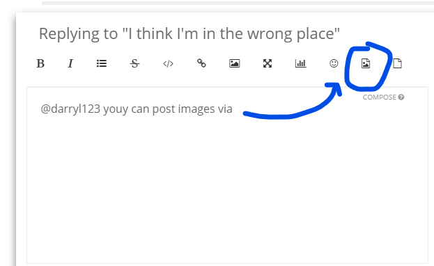
you might also find a service like imgur helpful- look at Desktop Website instructions
-
RE: Solved: Jogging past axis limits..?posted in CNC
@nightowl999
do you have and H564 statements in your homing macros ?formating: use three back ticks , the one under the ~, top left of your keyboard.
test
-
RE: Aluminum anodizing for IR probeposted in IR Height Sensor
I have black anodized aluminum under PEI and it works beautifully
-
RE: Secondary Dive height for probingposted in Firmware wishlist
@dc42 said in Secondary Dive height for probing:
@Hernicz are you saying that when doing multiple probes at the same point (i.e. the M558 A parameter is greater than 1), you would like the second and subsequent probes done using a lower dive height, as well as using a different speed?
If so, that sounds like a good idea to me and one that I am prepared to implement.:
Would you then reset the baseline for repeatability and tolerance checking too? Seems that would be in order as well.
But, I have to say that there is a pratical limit to all this and some of this is creating a false sense of precision....
Repeating the same dive height at the same point will only repeat the error of backlash in the mechnical system.
People are chasing phantom 0's just because the software believes that they are there.... 0.0025mm for example is just silly. People really don't understand what it takes to gauge this, let along repeat this measurement in the real world. The slightest breath will throw the needle on a gauge amplifier that much and more. There are reasons metrology is performed in controlled environments. A 3d printer is anything but.
-
RE: DuetWifi clones and supportposted in General Discussion
Duet predates the reprap movement. Anyone remember the Boxford CNC that you could stand up in mill configuration or lay flat for lathe?
-
RE: CNC Gui Thoughtsposted in CNC
@jay_s_uk said in CNC Gui Thoughts:
@3dpandme have you seen the diabase UI? This is what I use on my CNC https://github.com/diabase/H-Series-Web-Control/tree/3.4-dev
I also use their version of the paneldue interface that works with an encoderditto on Diabse's UI and pendant. for what it is, its nice and clean.
while a fully featured UI like UNCC would be nice, RRF was not purposefully written to be that. You might be happier and better served with LinuxEMC.
-
RE: Aluminum anodizing for IR probeposted in IR Height Sensor
It looked like lemon candy melted in a cast iron pan. Its hard to describe really.
I got a 0.030 piece of PEI from CS Hyde and laid up the anodized sheet under it. The top surface was all slick and glossy, like glass. It was really quite pretty actually. Polished gloss actually. It reflected light too well so I wet sanded it with 400 grit and then ran a maroon then white scotchbrite pad over it to break the surface.
-
RE: Make M558 parameters available for more Z-Probe movesposted in Firmware wishlist
@MaxGyver i use 2 kinds of probes on my CNC- an aligator clip to connect to the tool/touch-off plate for Z and a baby reinshaw type probe for X-Y.
the touch off plate will probe twice for setting Z.
the X-Y probe i think will only touch once.
I am not currently near that machine but will be over the weekend. i will try to make some experiments and report back.
sinneD
-
RE: What’s the stance on RRF on none Duet boards?posted in General Discussion
@blacksheep99 this has been discussed at length, many times over the years, both here and on reprap.org forums. if you do a bit of a searching you will see. I don't know if there IS an official position. Most people will say they justify the expense of the OEM hardware with the notion that part of the money goes towards RRF development, but I dont think anyone has proved that point.
dc42 has been very much supportive of ports to alternative hardware over the years. I think the first LPC port for 2.0.x was begun in 2017/2018, and he was instrumental to making that work. I think Tony did too. There was a LOT of work went into that to make RRF work on the limited hardware.
speaking for myself- as one who ran the then bleeding edge 2.0.x stuff on LPC boards there was no scorn or judgement from the main developers. they helped us get RRF running because I think the goal of expanding the collective userbase for RRF was more important than generating hardware sales.
I have printers that run on both OEM boards with expansion boards, and LPC based boards and expansion boards. The best comparison I could offer is think of it as an engine swap- you can stuff a V-8 into almost any car with varying amounts of adaptation, but its not nescessarily going to be a muscle car. Do you like the challenge of the mechanics or do yo want to drive?
Without a doubt, the OEM hardware is the most stable and reliable. You can convert an existing machine with an alternative board to run RRF but its not going to be the same. If you go into the adventure thinking you will save money by using alternative hardware- I think its a sense of false economy. You might spend 2/3 of what the equivalent OEM solutions are and end up with 75% of their funciton and ability. At the end of the day, its just not the same as the OEM hardware.
-
RE: Duex5 - 5v for relayposted in Duet Hardware and wiring
I had similar challenge. I ended up wiring up a MOSFET to be triggered by the pin. The MOFSET can get triggered by anything as low as 2.5V.
If you control the ground wire of the circuit, you can then use almost any relay, 5V or 12V. I am basically following the Duet schematic for the circuit. I described it here -
https://forum.duet3d.com/topic/10758/powering-on-using-tp-link-smart-plug
-
RE: Help with IR Probe on LPC Port pleaseposted in IR Height Sensor
ok, i think the issues is the pin that i am connected to is not analogue capable, its digital only.
i need to read the LPC docs more closely.
-
RE: Weird behaviour after first printposted in Beta Firmware
You have to call the probe deploy from within your homez and then again in your beg.g or other macros that need the probe. Conditonal gcode makes this an easy check and remedy.
The error is because the NC probe state is 1000 when the probe is not connected or triggered. you have to include in your macros the logic to address these states.
You should go look a the macros for Euclid Probe. We've been running this reliably for over 2 years at this point, both with fixed dock and moving bed pickups.
Also, we have found that inspecting the actual probe value is more reliable that checking the probe token in the object model. In the case of a mis-deploy, which is really rare with Euclid Probe, the probe value is more telling.
