Never mind. I got it working. The issue was with the time delays.
Chinese documentation:
M569 P41.0 S1 R1 T2.5:2.5:5:5
Reality:
M569 P41.0 S1 R1 T6:6:6:6
Never mind. I got it working. The issue was with the time delays.
Chinese documentation:
M569 P41.0 S1 R1 T2.5:2.5:5:5
Reality:
M569 P41.0 S1 R1 T6:6:6:6
@droftarts At first, I intended to use the 6XD, but I received a pre-wired and configured 6HC bundled with an extruder, so I thought adding 3x 1XD would be faster and cheaper than switching to the 6XD.
Never mind. I got it working. The issue was with the time delays.
Chinese documentation:
M569 P41.0 S1 R1 T2.5:2.5:5:5
Reality:
M569 P41.0 S1 R1 T6:6:6:6
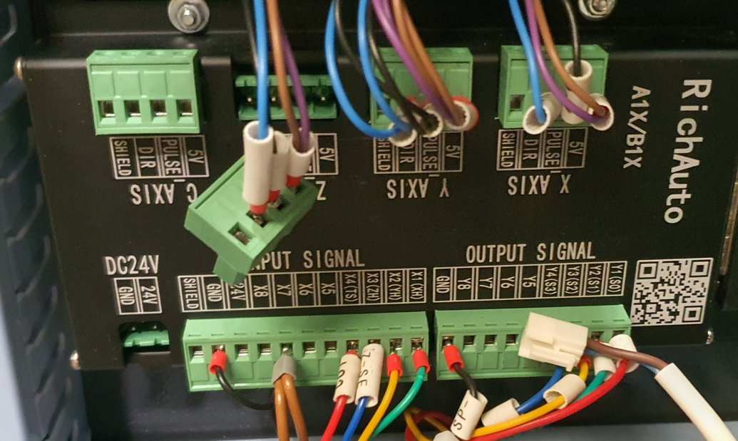
I am generally converting a CNC milling machine into a 3D printer. I want to replace the old motherboard (RichAuto A1X/B1X) with a Duet 6hc and 1xd modules.
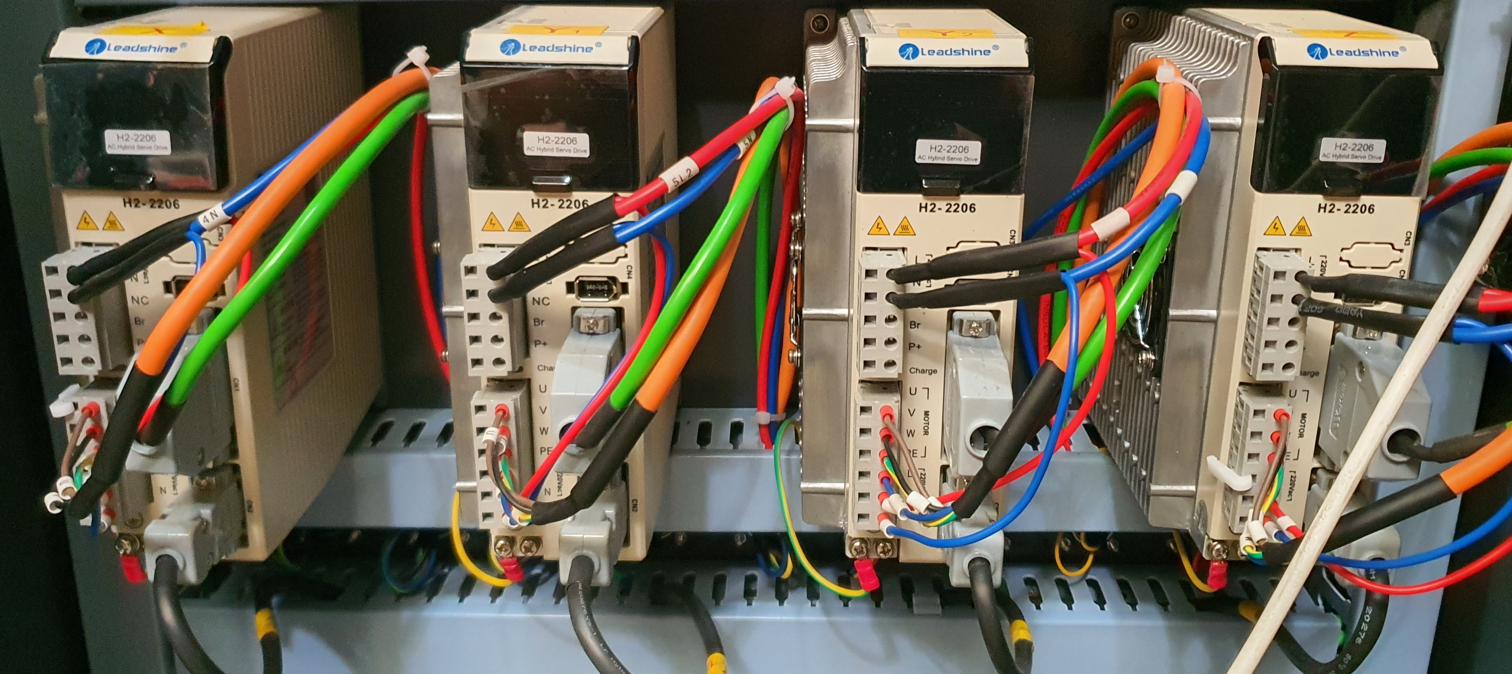
The motor drivers are H2-2206, and the servo motors are 863HSM100H. The documentation includes information about pulse times, and they are set in the firmware as follows:
M569 P41.0 S1 R1 T2.5:2.5:5:5
Regarding the connections, +5V is connected to 5V, STEP- to PULSE-, and DIR- to DIR-. The drivers do not have EN inputs.
; Configuration file for Duet 3 (firmware version 3.5.1)
; executed by the firmware on start-up
;
; SBC Config
M291 P"Applying persistent configuration options" R"Please wait" S1 T60 ; show that persistent settings are being configured
while exists(sbc) && plugins.DuetPiManagementPlugin.pid < 0 && iterations < 30
G4 S2 ; wait for DuetPiManagementPlugin to become available
G4 S2 ; wait another moment
M929 S2 ; start logging events to the SD Card
M550 P"MD" ; set persistent hostname for printer
;M551 P"mdrapid" ; set password
M586 P0 S1 C"*" ; configure HTTP & enable CORS
M586 P1 S0 ; disable FTP
M586 P2 S0 ; disable Telnet
M292 ; hide message box again upon completion
; General Preferences
G21 ; Work in millimetres
G90 ; absolute coordinates
M83 ; relative extruder moves
; Drives
M569 P41.0 S1 R1 T2.5:2.5:5:5 ; physical drive 0.0 goes forwards with active high enable config pulses intervals (x)
M569 P42.0 S1 R1 T2.5:2.5:5:5 ; physical drive 0.0 goes forwards with active high enable config pulses intervals (y)
M569 P43.0 S1 R1 T2.5:2.5:5:5 ; physical drive 0.0 goes forwards with active high enable config pulses intervals (z)
M584 X41.0 Y42.0 Z43.0 ; set drive mapping
M92 X83.50 Y83.50 Z320.00 ; set steps per mm
M566 X600.00 Y600.00 Z60.00 ; set maximum instantaneous speed changes (mm/min)
M203 X3000.00 Y3000.00 Z1800.00 ; set maximum speeds (mm/min)
M201 X500.00 Y500.00 Z20.00 ; set accelerations (mm/s^2)
; Axis Limits
M208 X0 Y0 Z0 S1 ; set axis minima
M208 X2000 Y4000 Z320 S0 ; set axis maxima
; Endstops
M574 X1 S1 P"io2.in" ; configure switch-type (e.g. microswitch) endstop for low end on X via pin io2.in
M574 Y1 S1 P"io3.in" ; configure switch-type (e.g. microswitch) endstop for low end on Y via pin io3.in
; Z-Probe
M558 P5 C"io5.in" H10 F900 T3000 ; set Z probe type to switch and the dive height + speeds
G31 P500 X0 Y0 Z8 ; set Z probe trigger value, offset and trigger height
M557 X0:1250 Y0:2400 S200 ; define mesh grid
; PE320 Extruder
M569 P40.0 S1 R1 T0:0:0:0 ; external drive CAN address 40 goes forward, active high enable
M584 E40.0 ; set drive mapping - map extruder to CAN address 40
M350 E1 I0 ; configure extruder with NO microstepping
M92 E301.6485 ; set steps per mm - extruder E-steps/mm (resolution of 1:48) or 166.7 steps/rev
M566 E3000 ; set maximum instantaneous speed changes (mm/min)
M203 E3000 ; set maximum speeds (mm/min)
M201 E20000 ; set accelerations (mm/s^2)
; Temp sensor parameters
M308 S0 P"2.spi.cs0" Y"rtd-max31865" A"Top"
M308 S1 P"2.spi.cs1" Y"rtd-max31865" A"Middle"
M308 S2 P"2.spi.cs2" Y"rtd-max31865" A"Bottom"
M308 S3 P"2.spi.cs3" Y"rtd-max31865" A"Nozzle"
; Create heaters
M950 H0 C"out0" T0 ; create Top heater output on out0 and map it to sensor 0
M950 H1 C"out1" T1 ; create Middle heater output on out1 and map it to sensor 1
M950 H2 C"out2" T2 ; create Bottom heater output on out2 and map it to sensor 2
M950 H3 C"out3" T3 ; create Nozzle heater output on out3 and map it to sensor 3
; Set PID heater parameters
M307 H0 R1.319 K0.319:0.000 D25.28 E1.35 S1.00 B0
M307 H1 R0.650 K0.120:0.000 D35.30 E1.35 S1.00 B0
M307 H2 R0.636 K0.188:0.000 D41.46 E1.35 S1.00 B0
M307 H3 R0.500 K0.137:0.000 D21.29 E1.35 S1.00 B0
; Maximum extruder heater temperature
M143 H0 S400 ; set temperature limit for heater 0 to 400C
M143 H1 S400 ; set temperature limit for heater 0 to 400C
M143 H2 S400 ; set temperature limit for heater 0 to 400C
M143 H3 S400 ; set temperature limit for heater 0 to 400C
; Extruder heater fault detection
M570 H0 P60 T30 ; An anomaly on heaters 0 must persist for 60 seconds, and must be greater or less than 30C from the setpoint, to raise a heater fault.
M570 H1 P60 T30 ; An anomaly on heaters 1 must persist for 60 seconds, and must be greater or less than 30C from the setpoint, to raise a heater fault.
M570 H2 P60 T30 ; An anomaly on heaters 2 must persist for 60 seconds, and must be greater or less than 30C from the setpoint, to raise a heater fault.
M570 H3 P60 T30 ; An anomaly on heaters 3 must persist for 60 seconds, and must be greater or less than 30C from the setpoint, to raise a heater fault.
; Define Heaters as Tools
M563 P0 H0 S"Top"
M563 P1 H1 S"Middle"
M563 P2 H2 S"Bottom"
M563 P3 D0 H3 S"Nozzle"
; Heater Cooling Fans
M950 F0 C"2.out0+io1.in" Q100 A"Heat Break Fan" ; Heat Break Fan -- 4-wire PWM 12V fan so invert it, 100Hz PWM, NO tacho
M950 F1 C"!2.out3+out3.tach" Q100 A"Top Fan" ; Top Fan -- 4-wire PWM 12V fan so invert it, 100Hz PWM, tacho connected
M950 F2 C"!2.out4+out4.tach" Q100 A"Middle Fan" ; Middle Fan -- 4-wire 12V PWM fan so invert it, 100Hz PWM, tacho connected
M950 F3 C"!2.out5+out5.tach" Q100 A"Bottom Fan" ; Bottom Fan -- 4-wire 12V PWM fan so invert it, 100Hz PWM, tacho connected
M106 P0 S1 T40 H0:1:2:3 ; Turn on Heat Break Fans when heaters 0-3 are above 40 deg
M106 P1 S0.5 ; Run at 20% speed at 2200rpm (max 11000rpm)
M106 P2 S0.5 ; Run at 20% speed at 2200rpm (max 11000rpm)
M106 P3 S0.5 ; Run at 20% speed at 2200rpm (max 11000rpm)
; Bed Heaters
;M308 S4 P"1.temp0" Y"thermistor" A"Bed" T100000 B4725 C7.06e-8 ; configure bed thermistor at 1.temp0
;M308 S5 P"1.temp1" Y"thermistor" A"Bed" T100000 B4725 C7.06e-8 ; configure bed thermistor at 1.temp1
;M308 S6 P"1.temp2" Y"thermistor" A"Bed" T100000 B4725 C7.06e-8 ; configure bed thermistor at 1.temp2
;M308 S7 P"temp0" Y"thermistor" A"Bed" T100000 B4725 C7.06e-8 ; configure bed thermistor at temp0
;M950 H4 C"1.out0" T4 Q10 ; create bed heater output on 1.out0 and map it to temp sensor 4
;M950 H5 C"1.out1" T5 Q10 ; create bed heater output on 1.out1 and map it to temp sensor 5
;M950 H6 C"1.out2" T6 Q10 ; create bed heater output on 1.out2 and map it to temp sensor 6
;M950 H7 C"1.out3" T7 Q10 ; create bed heater output on 1.out3 and map it to temp sensor 7
;M307 H4 R0.421 K0.321:0.000 D5.73 E1.35 S1.00 B0 ; Bed PID tuning parameters
;M140 P0 H4 ; map heater 4 to heated bed 0
;M140 P1 H5 ; map heater 5 to heated bed 1
;M140 P2 H6 ; map heater 6 to heated bed 2
;M140 P3 H7 ; map heater 7 to heated bed 3
;M143 H4 S120 ; max temp -- 120 deg C
;M143 H5 S120 ; max temp -- 120 deg C
;M143 H6 S120 ; max temp -- 120 deg C
;M143 H7 S120 ; max temp -- 120 deg C
;M570 H4 P60 T15 ; An anomaly on heaters 4 must persist for 60 seconds, and must be greater or less than 15C from the setpoint, to raise a heater fault.
;M570 H5 P60 T15 ; An anomaly on heaters 4 must persist for 60 seconds, and must be greater or less than 15C from the setpoint, to raise a heater fault.
;M570 H6 P60 T15 ; An anomaly on heaters 4 must persist for 60 seconds, and must be greater or less than 15C from the setpoint, to raise a heater fault.
;M570 H7 P60 T15 ; An anomaly on heaters 4 must persist for 60 seconds, and must be greater or less than 15C from the setpoint, to raise a heater fault.
; Define Bed Heaters as Tools
;M563 P4 H4 S"Bed 0"
;M563 P5 H5 S"Bed 1"
;M563 P6 H6 S"Bed 2"
;M563 P7 H7 S"Bed 3"
; Define Inputs
M950 J0 C"io0.in" ; Relay 12 - Estop
M950 J1 C"io1.in" ; Relay 13 - Reset
;M950 J2 C"io2.in" ; Relay 14 - X-Endstop
;M950 J3 C"io3.in" ; Relay 15 - Y-Endstop
;M950 J4 C"io4.in" ; Relay 16 - Z-Endstop
;M950 J5 C"io5.in" ; Relay 17 - Z-Probe
M950 J6 C"io6.in" ; Relay 18 - FREE
M950 J7 C"io7.in" ; Relay 19 - FREE
M950 J8 C"io8.in" ; Relay 20 - FREE
M950 J9 C"1.io0.in" ; Relay 21 - FREE
M950 J10 C"1.io1.in" ; Relay 22 - FREE
M950 J11 C"2.io0.in" ; Smart Wiring Loom - Material sensor LEFT
M950 J12 C"2.io2.in" ; Smart Wiring Loom - Material sensor RIGHT
M950 J13 C"40.io0.in" ; 1XD board - Servo Drive Fault
; Configure Input Triggers
M581 P1 T2 S1 R0 ; Relay 13 - trigger 2 (Reset) activates on falling edge when Estop button is pressed
M581 P13 T3 S1 R0 ; Trigger 3 (Servo Drive Fault) activates on falling edge when servo fault detected
; Define Ouputs
M950 P0 C"out4" ; Relay 1 - Pellet Material Feed Solenoid
M950 P1 C"out5" ; Relay 2 - Part Cooling Solenoid
M950 P2 C"out6" ; Relay 3 - FREE
M950 P3 C"out7" ; Relay 4 - FREE
M950 P4 C"out8" ; Relay 5 - FREE
M950 P5 C"out9" ; Relay 6 - FREE
M950 P6 C"1.out1" ; Relay 7 - FREE
M950 P7 C"1.out2" ; Relay 8 - FREE
M950 P8 C"1.out3" ; Relay 9 - FREE
M950 P9 C"1.out4" ; Relay 10 - FREE
M950 P10 C"1.out5" ; Relay 11 - FREE
M950 P11 C"40.io0.out" ; 1XD board - Clear Servo Drive Faults
; Set Outputs
M42 P0 S0 ; Output OFF
M42 P1 S0 ; Output OFF
M42 P2 S0 ; Output OFF
M42 P3 S0 ; Output OFF
M42 P4 S0 ; Output OFF
M42 P5 S0 ; Output OFF
M42 P6 S0 ; Output OFF
M42 P7 S0 ; Output OFF
M42 P8 S0 ; Output OFF
M42 P9 S0 ; Output OFF
M42 P10 S0 ; Output OFF
M42 P11 S0 ; Output OFF
; Select Tool
T3 ; select nozzle heater with PE320 extruder
M568 P3 A0 ; set nozzle heater to off
; Custom settings
https://www.control-drive.com/Documents/Manuals/CN/H2-2206_manual_cn.pdf
https://www.scribd.com/document/717854727/H2-2206-manual-cn
https://forsuncnc.com/wp-content/uploads/2021/11/DSP-A11-User’s-Manual.pdf
This is the second milling machine I am converting into a 3D printer. The previous one was very similar, and it works correctly. The motor drivers there were H2-758. I also connected only 5V, Step-, and Dir- there. I used Duet 6xd there. When I measure the step signal during movement there, it shows 0.5V, which is more than on 1xd.
Hi,
I am connecting a stepper motor driver via the Duet 1XD module to the driver out outputs: +5V, step-, and dir-. When I click on the +50 or -50 shift on the panel, nothing happens.
After measuring the voltages with a multimeter on +5V and dir-, it shows 5V, and after changing the direction of movement, it shows 0V (which is correct).
When measuring the voltage between +5V and step-, it shows 0V, and when I click on the +50 or -50 shift on the panel, the voltage changes briefly to 0.05V (while it should change to 5V). What could be the cause?