@matt3o I hope you solve the problem you are having!
The bowden tube is ~680 with the current position of the extruder.
Posts made by nuverian
-
RE: KEEVO v2 (corexy 3d printer)posted in My Duet controlled machine
-
RE: KEEVO v2 (corexy 3d printer)posted in My Duet controlled machine
@matt3o Thanks I guess
 Haha. Your printer design looks really great!
 -
KEEVO v2 (corexy 3d printer)posted in My Duet controlled machine
Hello again,
I finally was able to update the project and bring it to a state which I now consider finished (although no printer is really ever "finished"
 ) I am very happy with the end result and has proven to be a reliable machine.
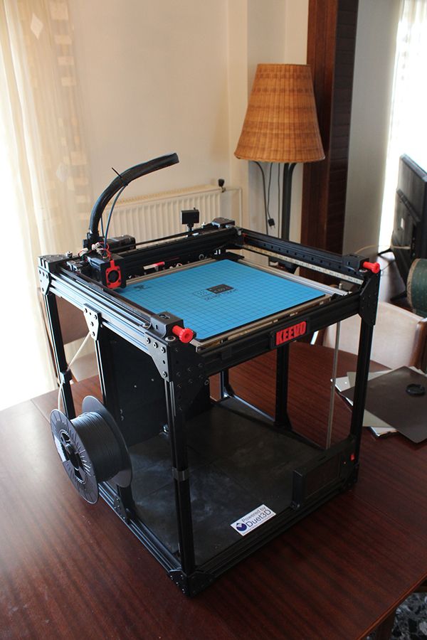
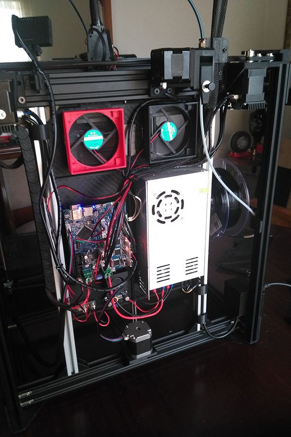
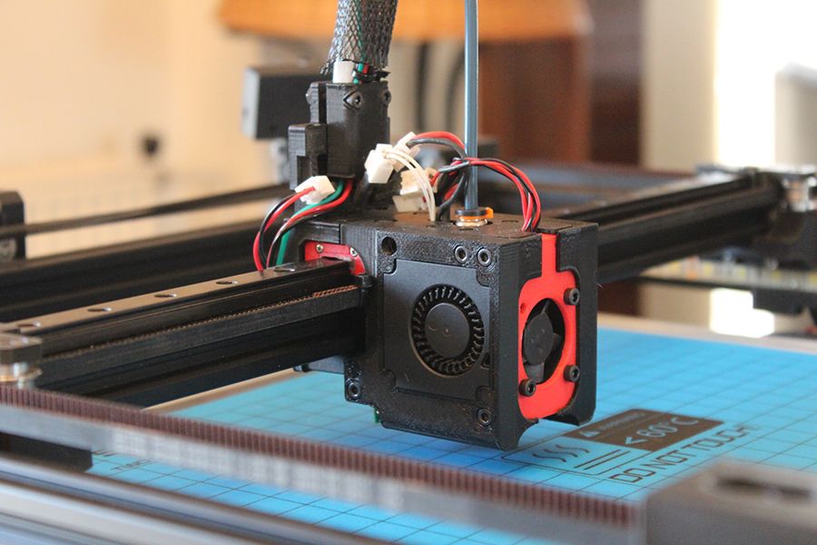
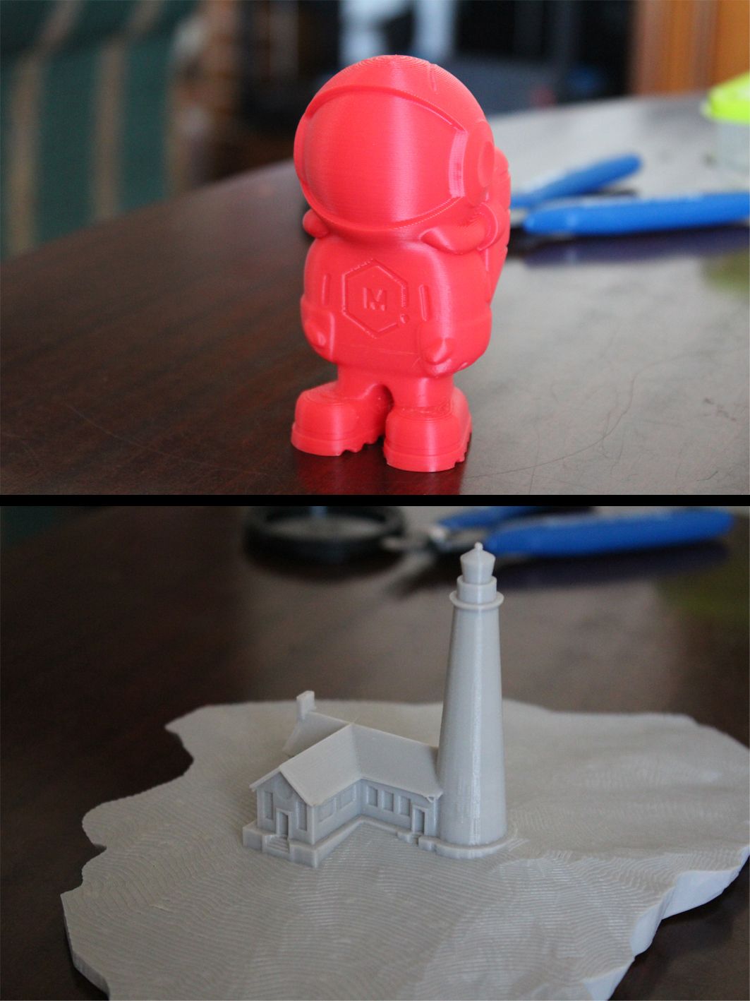
Some KEEVO printed parts:
I hope you like it. If you see any apparent improvements that can be made to the design, please let me know! The project can also be found on thingiverse: https://www.thingiverse.com/thing:4129443
Cheers!
-
RE: KEEVO Printer (corexy)posted in My Duet controlled machine
Thanks for your comments.
I ended up adding a counter bearing on the bottom to help with the belt forces, as well as a collar on the leadscrew above the pillow bearing to help with vertical/gravity forces. -
RE: KEEVO Printer (corexy)posted in My Duet controlled machine
@Phaedrux Hey thanks!
Great printer you have as well
 Similar Z concepts. I see you use two bearings (as far as I understood). Was that for the same reason and for peace of mind?
I also don't think it will be a problem, but what I was thinking is adding a counter bearing on the bottom so that when the belt pulls, the leadscrew won't budge. Something like this mockup:
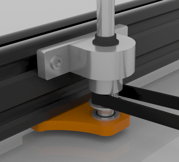
Maybe an overkill, maybe not

-
KEEVO Printer (corexy)posted in My Duet controlled machine
Hello again,
I just wanted to share with you the last build I made, which of course uses Duet

(KEEVO = Cube in Greek)
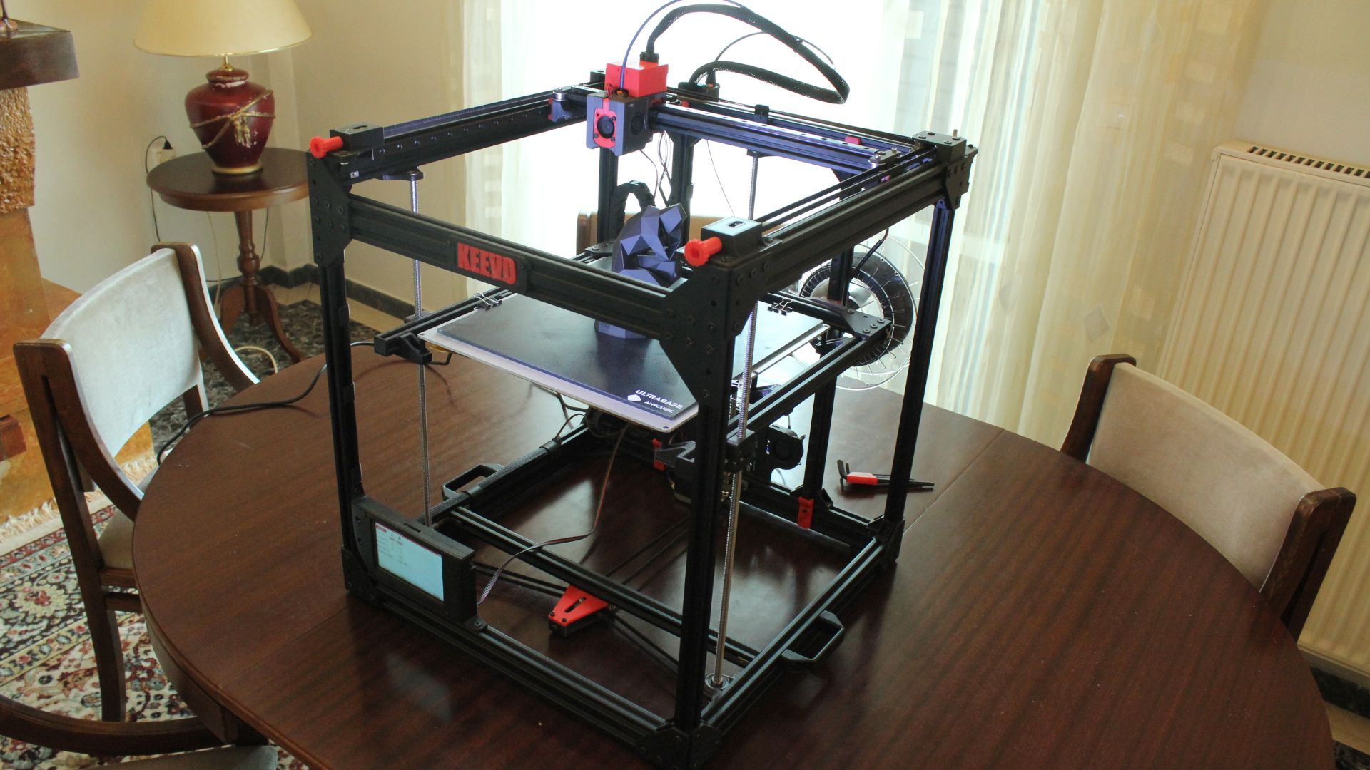
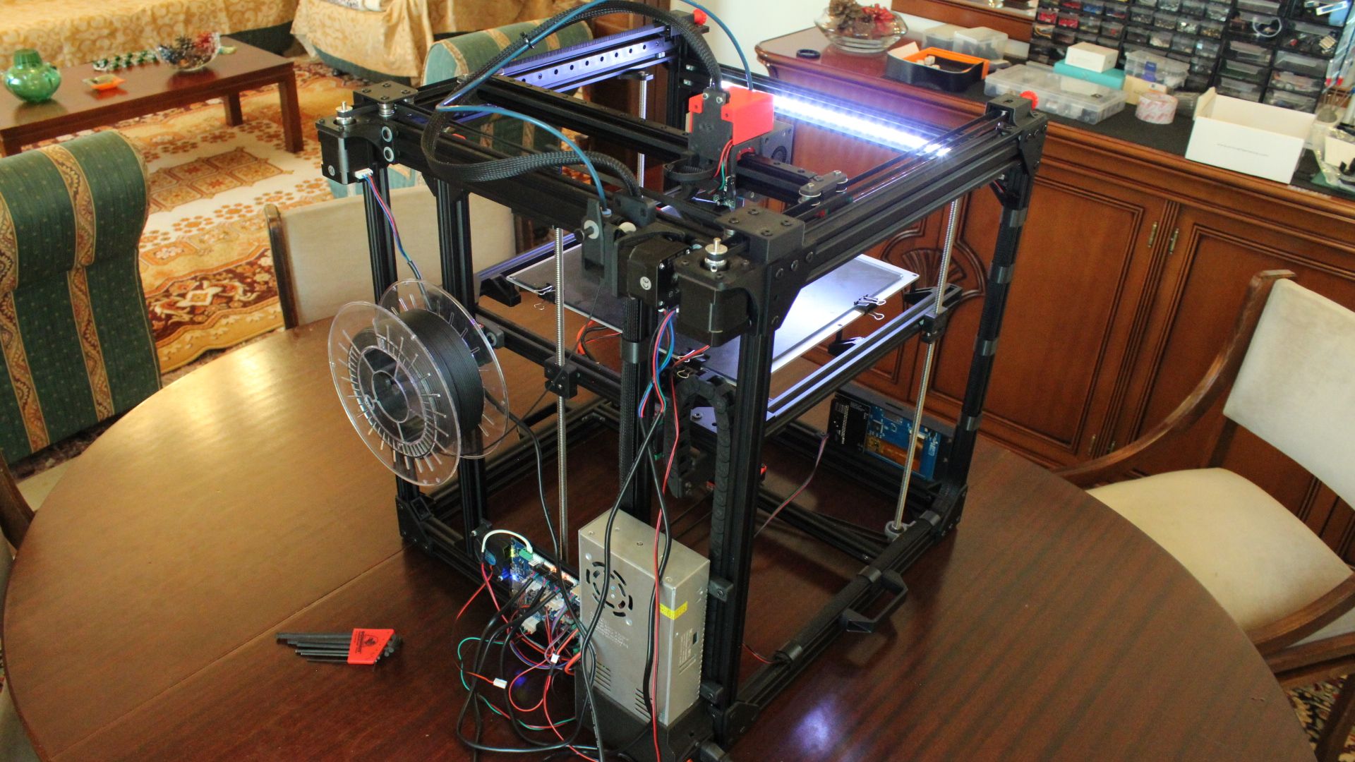
(yeah the cables need some management)It is also posted on Thingiverse -> https://www.thingiverse.com/thing:4129443
Any feedback is welcome of course!
Also, regarding the 3 leadscrews (which are only really mounted on the bottom), do you think that the forces from the Z belt will bend the leadscrews in the long run. I don't really see any bending though. It can be seen more clearly in this video which was the previous version (an hbot without duet and other stuff, but z axis is the same) -> https://www.youtube.com/watch?v=K0pcGKAQ4eA
Cheers

-
RE: 400W Heated Bed.posted in Duet Hardware and wiring
@bearer
So, I did the test and that confirms it

I incrementaly heated up the bed at target temp each time, unplug and measure it. Done at 21v although I don't think that matters much for this.- 28C - 1.45 (my room temp)
- 40C - 1.53
- 50C - 1.63
- 60C - 1.65
- 70C - 1.72
- 80C - 1.72
It is interesting to see that at about 50-60 C the resistance does not change much. Also at least in my test, the resistance stayed the same at 70C - 80C, so I presume that about 70C the max change has been reached.
Thanks a lot for I learned something new!
-
RE: 400W Heated Bed.posted in Duet Hardware and wiring
Thanks @bearer .
I will do your suggested test (heat -> measure -> heat -> measure) tomorrow and let you know what resistance measurements I came up with
-
RE: 400W Heated Bed.posted in Duet Hardware and wiring
Thank you both for extra information and help.
I decreased the power supply voltage for now, but I will order an SSR to do the switching, since I am losing about 100W bed heating power (down to 300W from 400W now). It's a DC 300x300mm PCB bed by the way.
I wouln't want to change the fuse to a 20A since 18A is the Duet rated max (better safe than sorry).
Thanks again

-
RE: 400W Heated Bed.posted in Duet Hardware and wiring
Thank you both for your answers.
Would doing what @bearer suggests (M303 I presume rather than M203), actually warrants that the drawn current will stay within calculated max, set by the P parameter, or full current will be drawn at the start of the heating up?
Otherwise I will just lower the voltage, yeah

Thank you!
-
400W Heated Bed.posted in Duet Hardware and wiring
Hello again,
I have a 24v, 400W heated bed (actual measurment of 1.45 Ohms) and thus, it should draw about 16.5 Amps.
Now while the max heated bed current in Duet is 18A, the fuse and for a good reason is 15A.Things I am considering:
- Use an external mosfet or SSR to do the switching?
- Is there an firmware option to limit the power the bed draws?
* Increase the resistance with a shunt/power resistor? - Would it be a good solution to drop the power supply output voltage to 21v (thus make the bed draw about 14.5 Amps) ? I use a single power supply for all electronics though.
What are your thoughts?
Thanks!
-
RE: Combine Tool Wiringposted in Duet Hardware and wiring
@pawprinter This is lovely. Super compact (even more than I'd imagine using JST XH). The double sided idea is a very good one. I might just steal it with your permision

@dc42 Yep, that is understandable, hence the reason why I was thinking JSTs (separate and with correct orientation), but then again, this is uber compact if that is the uter goal, along with it's potential shortcomings that is.
Thanks for your replies everyone!
-
RE: Combine Tool Wiringposted in Duet Hardware and wiring
Hey, thanks. That looks like a good wire indeed, but unfortunately the problem for me, is not actually the number of wires per-se, but rather the number of connectors entirely for spacing reasons. Right now I use these NPP wire-to-wire connectors (https://grobotronics.com/wire-connector-npp-4-pin-female-2.5mm.html?sl=en), and each one is taking up quite some space (for no good reason). Of course I could always not use wire connectors but I want to 100%.
Thus I thought of creating a small distrubution board on a prefboard with all wires from board directly soldered in and leading to JST XH connectors for heater, fans etc. The whole assembly seems to take much less space than all the NPP connectors I am using now. I also thought of using JST XH wire-to-wire, but it's not really good idea I think.
Maybe there are some type of very small wire-to-wire connectors I do not know. -
RE: Combine Tool Wiringposted in Duet Hardware and wiring
Thank you for the link.
So from the looks of it, I need 10 wires, or 9 if I do use stall detection instead of switch, but I am not sure yet. I feel safer with limit switches.
A simple distribution board is exactly what I am trying to make BTW. Using serial on the head sounds very nice for v3 (but I have v2), so I will have to roll some sort of custom, yet simpler solution.Thanks!
-
Combine Tool Wiringposted in Duet Hardware and wiring
Hello,
New Duet Wifi user here trying to figure out how to combine the wiring going to the toolhead, or in other words what are the minimum number of wires I need to "send" to the toolhead.
These are the things that need connecting:
- Heater.
- Thermistor.
- Hotend Fan.
- Part Fan.
- Limit Switch (NC).
- dc42's IR Sensor.
I understand that Heater and the two Fans, need 4 wires (1 positive and 3 negative) considering I do understand correctly that switching is happening on the negative side (?), but I am not sure about the rest.
Any help is appreciated.
Thanks!