I have tested the new version and I have to say it really is a huge improvement. For me, it's the best and most important update so far. My printer is heavy and has quite a high mass that is being moved. Now I can increase the acceleration and jerk with higher print speeds and a much better surface as a result. The printer used to make a lot of noise, especially when changing direction quickly (contours of figures etc.), which is no longer the case. In short, my printer now finally prints the way I always imagined it would, in terms of speed, noise and quality. Thank you for the release and the work involved.
Posts made by N3XT3D
-
RE: RepRapFirmware 3.6.0-alpha.2 for Duet main boards availableposted in Beta Firmware
-
RE: Bed Origin and axis Limitposted in Using Duet Controllers
@engikeneer this is really a clever solution. Exately what I was looking for! Thanks

-
RE: Bed Origin and axis Limitposted in Using Duet Controllers
@mrehorstdmd Yes 1-2 mm are definitely not a problem. For me, it's all about being able to reach a brush that is outside of the printable area, for example. That's all

I think I'll then shorten the flag as much as necessary so as not to complicate things.
Thank you for the hard work and the detailed answers.
Have a nice weekend.
-
RE: Bed Origin and axis Limitposted in Using Duet Controllers
First of all, thank you for all the help.
ok maybe there were too many different views. Sorry
At first I thought I would leave the flag longer and I can shorten it later, but then I thought why not leave it longer and relate the minimun of the axis to the trigger point. Too short wouldn't be good either.
My idea is to leave the flag a little longer (not necessarily as much as in the illustration. Let's say 5mm) and to use the "softlimit" to limit the axis so that it does not reach the mechanical end stop.
Maybe I'm just confused, but is it possible to say that the limit of an axis is 5mm behind the trigger?
-
RE: Bed Origin and axis Limitposted in Using Duet Controllers
@mrehorstdmd But even with this variant there is the problem that you can never drive past the trigger point of the end stop. Or am I wrong?
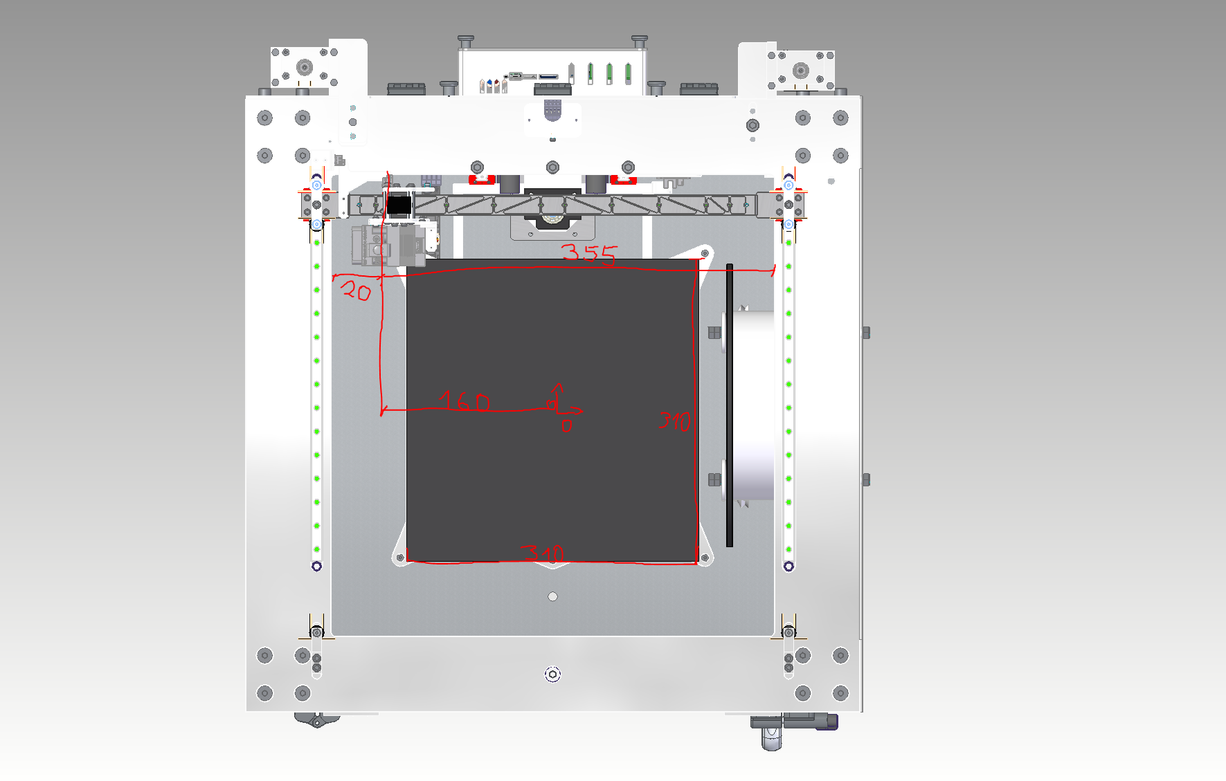
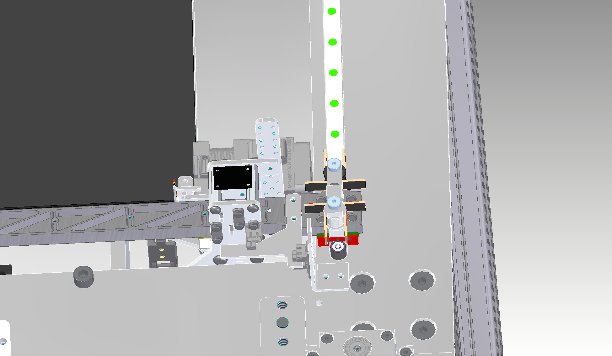
For example, these two views would be the point at which the optical end stop triggers. You couldn't go any further into the negative and I wouldn't be able to use 20mm of the rail


As an example for the X axis, the limit of the axis and the origin of the bed would have to be set separately (in relation to the trigger point of the respective axis).

Otherwise it would not be possible to use the entire length of the rail, as shown in the next picture

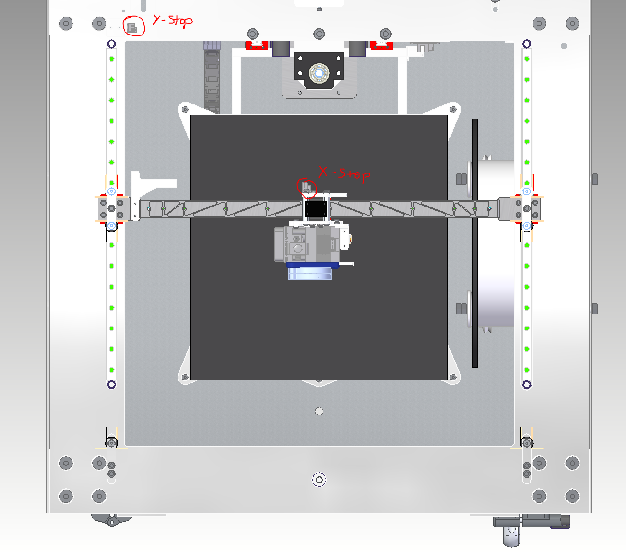
I hope the screenshots from the different perspectives and what I want to explain are understandable.
-
RE: Bed Origin and axis Limitposted in Using Duet Controllers
@mrehorstdmd Thanks for the tips.
Putting the origin point in the center of the bed should solve the problem.
I will leave the endstop layout as it is for the time being, as I already have some lasered aluminum parts here. But basically a good idea.
By the way, I have read some of the articles on the layout of Corexy printers and I would like to thank you for them.
This is the most helpful information you can get.So thank you

-
Bed Origin and axis Limitposted in Using Duet Controllers
Hello everybody.
For my new 3d printer project (Duet 2 Wifi), I installed optical end stops, which allow me to move the min and max of the axes beyond the trigger point.
This enables me to move each axis safely within its limits. However, this also has a direct effect on the bed origin point.Is it possible to set this independently, for example to reach a brush outside the print bed?
Thanks in advance

-
RE: Help needed with Duet 3 6hc TMC5160 StealthChop configposted in Tuning and tweaking
I have read through the documentation and will test and report it.
-
RE: Help needed with Duet 3 6hc TMC5160 StealthChop configposted in Tuning and tweaking
The volume is actually extremely loud throughout.
The faster the speed, the more extreme it becomes. If you print a cylinder with only one perimeter as a spiral, you will see very strong resonances in the print image due to the constant change in the speed of the motors due to the Corexy structure.
At some speeds the resonances are stronger, e.g. at 30mm/s at 60mm/s, on the other hand, the printer is "quietest", which is also outside the normal range. I have adjusted the M569 F parameter and tested between 1-10 during operation and at a standstill. The result would definitely be small.
I don't know how else to configure Coolstep, but I would definitely try it out. -
RE: Help needed with Duet 3 6hc TMC5160 StealthChop configposted in Tuning and tweaking
Exactly, I cross-checked via the console and the M350 command whether the parameters are active.
-
RE: Help needed with Duet 3 6hc TMC5160 StealthChop configposted in Tuning and tweaking
I used 16x micro stepping with interpolation. The change to 1.8 ° stepper motors brought some improvement, reducing the motors to 1A as well. The motor dampers made the printer quieter, but the vibration in the motor is so strong that you can even see it in the printed part.
This is my config.g
; Configuration file for Duet WiFi (firmware version 3) ; executed by the firmware on start-up ; ; generated by RepRapFirmware Configuration Tool v2.1.4 on Sat Dec 28 2019 21:53:43 GMT+0100 (Mitteleuropäische Normalzeit) ; General preferences ; Aktuelle Duet Wifi Firmware Version: 3.1.0 - Stand: 17.05.2020 ; Paneldue Information: Hardware Version: Panel Due v3.0a - 57600 baud - aktuelle Version: 1.24 - Stand: 11.05.20 M575 P1 S1 B57600 ; set Panel Due Baudrate to 57600 G90 ; send absolute coordinates... M83 ; ...but relative extruder moves M550 P"XY Cube" ; set printer name M667 S1 ; select CoreXY mode ; Network M552 S1 ; enable network M586 P0 S1 ; enable HTTP M586 P1 S0 ; disable FTP M586 P2 S0 ; disable Telnet ; Drives M569 P0 F3 S1 ; physical drive 0 goes forwards - Changed TOFF for reduced motor noise F4 is default M569 P1 F5 S1 ; physical drive 1 goes forwards - Changed TOFF for reduced motor noise F4 is default M569 P2 F3 S1 ; physical drive 2 goes forwards - Changed TOFF for reduced motor noise F4 is default M569 P3 S1 ; physical drive 3 goes forwards M584 X0 Y1 Z2 E3 ; set drive mapping M350 X16 Y16 Z16 E16 I1 ; configure microstepping with interpolation M92 X200.1 Y200.1 Z1600.00 E412.493 ; set steps per mm M566 X500.00 Y500.00 Z30.00 E400.00 ; set maximum instantaneous speed changes (mm/min) M203 X12000.00 Y12000.00 Z150.00 E2100.00 ; set maximum speeds (mm/min) M201 X2000.00 Y2000.00 Z100.00 E5000.00 ; set maximum accelerations (mm/s^2) M204 P1000 T2000 ; set accelerations of printmoves to 1000 and for travelmoves to 2000 (mm/s^2) M906 X1600 Y1600 Z1600 E1600 I30 ; set motor currents (mA) and motor idle factor in per cent ; M593 F32 ; Set Dynamic Acceleration to cancel ringing at 48 Hz M84 S30 ; Set idle timeout M671 X30:270:30:270 Y270:270:30:30 P0.7 ; Define Bedleveling screws, 0,7mm pitch ; Pressure advance M572 D0 S0.07 ; Pressure advance - 0.113 ; Axis Limits M208 X-11 Y0 Z0 S1 ; set axis minima M208 X306 Y321 Z500 S0 ; set axis maxima ; Endstops M574 X1 S1 P"xstop" ; configure active-high endstop for low end on X via pin xstop M574 Y2 S1 P"ystop" ; configure active-high endstop for high end on Y via pin ystop M574 Z1 S2 ; configure Z-probe endstop for low end on Z ; Z-Probe M558 P1 C"zprobe.in+zprobe.mod" H3 F100 T12000 I0 B0 ; set Z probe type to unmodulated and the dive height + speeds - A5 S0.02 optional fuer multiprobe selbsttest G31 P500 X-2 Y-16.4 Z3.05 ; set Z probe trigger value, offset and trigger height - 3.05 for CFK; 3.02 for Buildtak; 2.724 for Powdercoated Springsteel; 3.152 for ALU - Wert kleiner wird Abstand Größer. M557 X30:270 Y30:270 S40 ; define mesh grid ; Heaters M308 S0 P"bedtemp" Y"thermistor" T100000 B3950 A"Druckbett" ; configure sensor 0 as thermistor on pin bedtemp - A"Printbed" M950 H0 C"bedheat" T0 ; create bed heater output on bedheat and map it to sensor 0 M143 H0 S100 ; set temperature limit for heater 0 to 100C M307 H0 A154.1 C2269.2 D1.0 V24.0 B0 S1.00 ; disable bang-bang mode for the bed heater and set PWM limit M140 H0 ; map heated bed to heater 0 M308 S1 P"e0temp" Y"thermistor" T100000 B4725 C7.06e-8 A"Nozzle" ; configure sensor 1 as thermistor on pin e0temp - A"E3DV6 Hotend" M950 H1 C"e0heat" T1 ; create nozzle heater output on e0heat and map it to sensor 1 M143 H1 S280 ; set temperature limit for heater 1 to 280C M307 H1 A368.0 C157.4 D3.7 V24.0 B0 S1.00 ; disable bang-bang mode for the nozzle heater and set PWM limit ; Fans M950 F0 C"fan0" Q250 ; create fan 0 on pin fan0 and set its frequency M106 P0 C"Bauteil Lüfter" S0 H-1 ; set fan 0 name and value. Thermostatic control is turned off M950 F1 C"fan1" Q500 ; create fan 1 on pin fan1 and set its frequency M106 P1 C"Heatbreak Fan" S1 H1 T45 ; set fan 1 name and value. Thermostatic control is turned on ; Tools M563 P0 D0 H1 F0 ; define tool 0 G10 P0 X0 Y0 Z0 ; set tool 0 axis offsets G10 P0 R0 S0 ; set initial tool 0 active and standby temperatures to 0C ; Limit axis movement M564 H1 S1 ; movements only work with homed Axis; H1 = forbid movement of axes that have not been homed; S1 = limit movement within axis boundaries ; Custom settings are not defined M912 P0 S-4 ; Set correction for CPU Temperature ; Miscellaneous M911 S23 R28 P"M913 X0 Y0 G91 M83 G1 Z1 E-1 F1000" ; set voltage thresholds and actions to run on power loss -
RE: Help needed with Duet 3 6hc TMC5160 StealthChop configposted in Tuning and tweaking
@dc42 First of all, thank you very much for the detailed answer.
Then I probably misunderstood that in principle. I thought you couldn't activate stealth chop at all. Unfortunately I can hardly assess how loud this jolt is. My wish would be to be able to print up to 100mm / s (maximum) in the steahlthchop and to be able to switch to the spreadcycle for the travel speed.
Does the jolt depend on the Coolstep function? Or to put it another way, would this jolt also occur with the TMC 2209 drivers under the same conditions? I tried to find a couple of videos on Youtube that have a Duet 3 board built in to get an impression of what they sound like, but you can't find anything useful.Because with my printer with Duet 2 Wifi I have the problem that the printer without a stepper motor damper for X and Y is not acceptable because of the noise. I already reported on this in this forum. Here is the video too.
https://www.youtube.com/watch?v=jcsMTAzeeRE&t=2s
From this state I would like to turn off without "cheating" with the dampers. Otherwise I love the board and really don't want to leave the Duet boards. Therefore the consideration of switching to a Duet 3 board.
-
RE: Help needed with Duet 3 6hc TMC5160 StealthChop configposted in Tuning and tweaking
I really like the Duet boards, the build quality and firmware are great. But if an SKR board with TMC 2209 drivers manages to be that quiet, I don't think that should be a problem with the Duet. The Stealth Chop 2 function is the same. It is crucial for me that my printer should be quiet. So if nothing can change in the current situation, at least that's how I understood it, it will probably not be worth switching to the Duet 3 board for me. Please correct me if I have misunderstood or told something wrong.
-
RE: Help needed with Duet 3 6hc TMC5160 StealthChop configposted in Tuning and tweaking
I am thinking of buying the Duet 3 board. Does activating stealth chop now work without any problems?
-
RE: Very loud stepper motorsposted in My Duet controlled machine
@Phaedrux said in Very loud stepper motors:
That's a substantial difference!
Absolutely. This is really crazy. Thanks to all for the help. Now I am happy.

-
RE: Very loud stepper motorsposted in My Duet controlled machine
@theruttmeister so the problem with the noise no longer exists.
The dampers have had a huge impact. But the change from the 0.9 ° step angle to the motors with 1.8 ° step angle had an equally great effect. Many thanks for the help. Here is the video with the current state.
The printer is now quieter and faster, with the same current for the motors.
-
RE: Very loud stepper motorsposted in My Duet controlled machine
@theruttmeister I also believe that these minimal deviations from the 200 steps / mm are negligible.
Thank you for the detailed and very instructive explanation!
So I'll try the motor dampers first. If that does not bring the desired success, I will test the other motors.
The NEMA 23 motors are a bit too big for my printer. Even if it is processed relatively sturdy, it would not be able to withstand the resulting forces without the printing result suffering.
It doesn't have to be whisper-quiet, but you shouldn't be able to hear the printer 3 rooms further at 200 mm/s.
In a rented apartment, printing overnight is so completely impossible, which I would like to do. In addition, the loud noises of the printer in the apartment are very disturbing in the long run. I would be absolutely satisfied with a normal noise level.In any case, thank you for the help and the effort with the explanation. Really great. I will report what the change brought with the dampers.
-
RE: Very loud stepper motorsposted in My Duet controlled machine
@zapta said in Very loud stepper motors:
@N3XT3D said in Very loud stepper motors:
I will buy and try such dampers.
They work very good on my HEVO and significantly reduced the noise. You can estimate the expected noise reduction by removing the belt and then running the motor, once attached to the frame and once held in your hand.
BTW, I like your printer.
Many thanks. I will install the dampers tomorrow as soon as they are in the mail. I will then link a video with the current status. I hope that the dampers bring the hoped-for success.
-
RE: Very loud stepper motorsposted in My Duet controlled machine
@Phaedrux said in Very loud stepper motors:
@N3XT3D said in Very loud stepper motors:
I don't know if the motor in the rubber damper can't move too much.
It's actually quite stiff rubber. I don't think you'd get much more flex then you would from belts.
Thank you. I will buy and try such dampers. At the other end of the motor shaft I have a ball bearing for stiffening. If the damper is installed, the motor shaft will probably no longer reach into the ball bearing. But I will definitely test and report it.
-
RE: Very loud stepper motorsposted in My Duet controlled machine
@theruttmeister I use 16 teeth aluminum pulleys. With these values of steps / mm I get the best dimensional accuracy of the printed parts. I also find it strange that these values are not identical. They are nominal 6mm wide GT2 belts.
The speed of the printer is a nice to have for me, but the main thing for me is to reduce the noise.
I thought that if I lower the amperage of the motors, I only lose the motor's holding power and not my speed. Ok, as the speed of the motor increases, the holding force also drops a bit, but I think the effects are not that big.
What would be more sensible to install a large, powerful, new motor like this 65Ncm and operate it with lower amperes (because of the volume and still maintain the holding power) or to provide the current motors with dampers and maintain the 1600 mA? It would be important to me not to lose anything in accuracy. I don't know if the motor in the rubber damper can't move too much.